RK3576Encoder Board
Project: Board Introduction | page_id: 1823
| Board silkscreen model | RK3576-UHDENC_V10 |
|---|---|
| CPU RK3576 | 4×Cortex-A72 @ 2.2GHz + 4×Cortex-A53 @ 2.0GHz |
| MCU/GPU | ARM Mali-G52 MC3 |
| ISP | 16MP ISP, HDR, 3DNR, supports 3× MIPI CSI-2 |
| NPU Computing Power | 6 TOPS @ INT8 |
| DSP | Cortex-M0 + Audio Processing Unit |
| Storage | LPDDR4/LPDDR4X/LPDDR5, 32-bit; UFS 2.0/eMMC 5.1 |
| Encoding performance | H.264/H.265, up to 4K@60fps |
| Decoding performance | H.265/VP9/AV1/AVS2 up to 8K@30fps or 4K@120fps |
| Stitching | Supports multi-channel video processing/stitching; the specific capability depends on the SDK and solution |
| Video Input | 3× MIPI CSI-2 + DVP |
| Video Output | HDMI 2.1 / DP 1.4 / eDP 1.3 / MIPI DSI-2 |
| Network ports | 2× Gigabit Ethernet MAC (RGMII) |
| Peripheral interfaces | USB3.x/USB2.0, PCIe2.1, SATA3, CAN FD, UART, SPI, I²C/I³C, etc. |
| Storage interfaces | LPDDR4/4X/5, UFS2.0, eMMC5.1, SD3.0, SPI NOR/NAND |
| SDK | Android / Linux / RKNN |
| Power Consumption | Depends on workload and board-level design; it is not recommended to specify a fixed SoC power consumption |
| Package | FCCSP698L, 16.1 × 17.2 mm, 0.6 mm pitch |
| Operating Temperature | 0~80°C (SoC Datasheet); industrial modules can support -40~85°C |
| Service Life | Continuous operation service life greater than 2 years |
I. Board Introduction
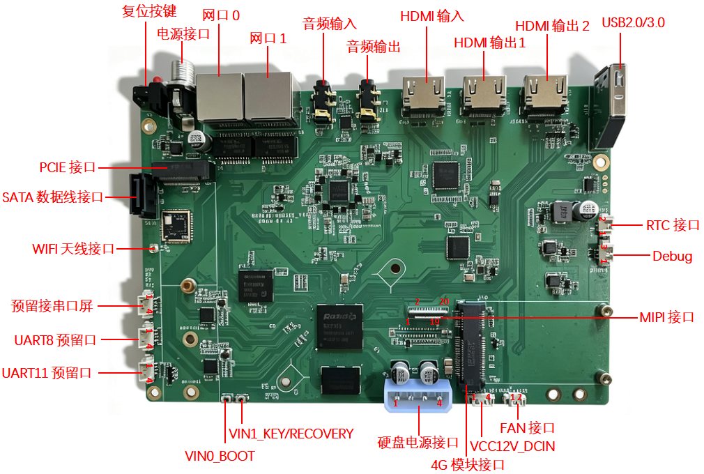
Board dimensions: 175*115mm
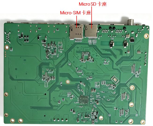
II. Chip Specifications
RK3576
Description
• iFPD, industrial control and gateways, cloud terminals, face recognition devices, in-vehicle central control, commercial displays
Features
Translation
CPU
• Quad-core Cortex-A72 + quad-core Cortex-A55, up to 2.2GHz
GPU
• ARM G52 MC3
NPU
• 6TOPS RKNN
PQ
•Rockchip dedicated Picture Quality Engine (HDR, ACM, DCI, etc.)
Display
• DisplayPort/MIPI/eDP/HDMI/RGB/EBC , multi-screen different display
Memory
• 32bits LPDDR4/4x, LPDDR5
• UFS 2.0 (2-lane), eMMC 5.1, SPI Nor/Nand
Video
• 8K30 H.264/H.265/VP9/AV2/AVS2 Decoder
• 4K60 H.264/H.265 Encoder
Camera
• 16M ISP with HDR (up to 120dB)
• MIPI CSI-2 (CDPHY=14-lane, DPHY=24-lane/42-lane), DVP
Interfaces
• 5 SAI interfaces (total 7-tx and 7-rx lanes, each lane supports 8-ch I2S/PCM/TDM)
• 2 PCM (2*8-ch)
• 2 S/PDIF TX and 1 S/PDIF RX
• ASRC
• USB 3.0 DRD (supports Alt mode with DP)
• Combo USB3.0 DRD/PCIe 2.1 RC/SATA3
• Combo PCIe 2.1 RC/SATA3
• RGMIIx2
• CAN FD, DSMC
• UART, SPI, PWM, I2C, SAR-ADC
III. Board Interface Diagram
1. Power interface
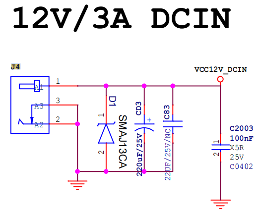
2. Debug
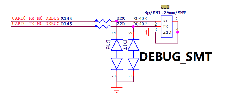
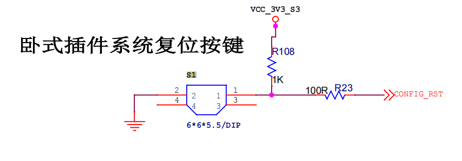
3. Reset button
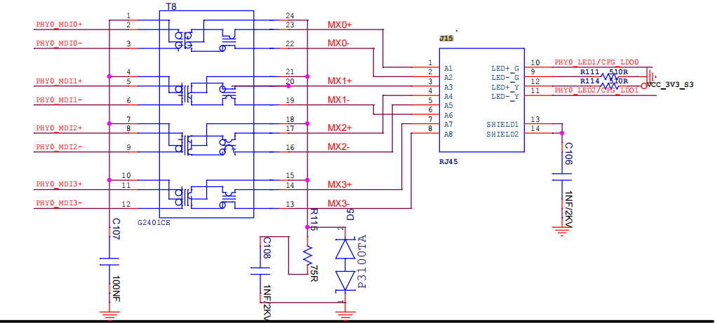
4. Network port 0
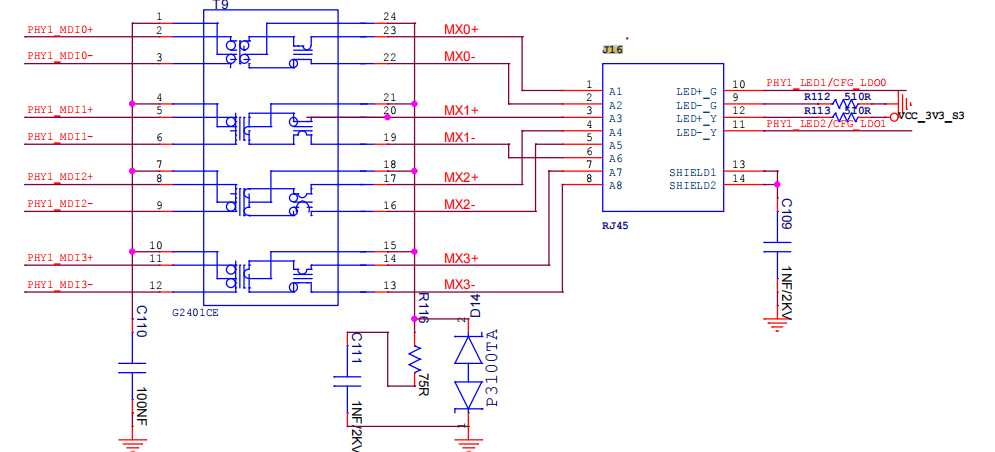
5. Network port 1
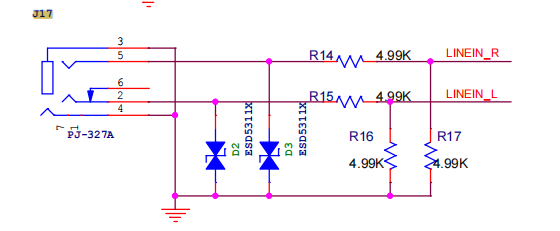
6. Audio input
7. Audio output
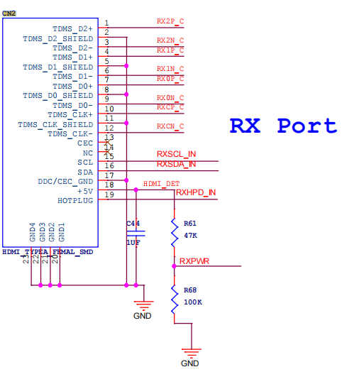
8. HDMI input
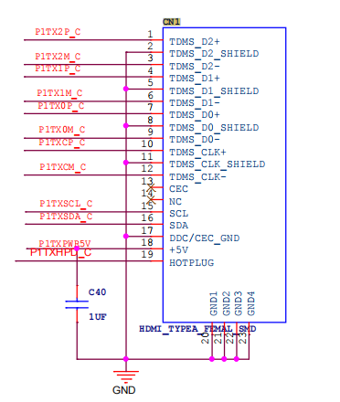
9. HDMI output 1
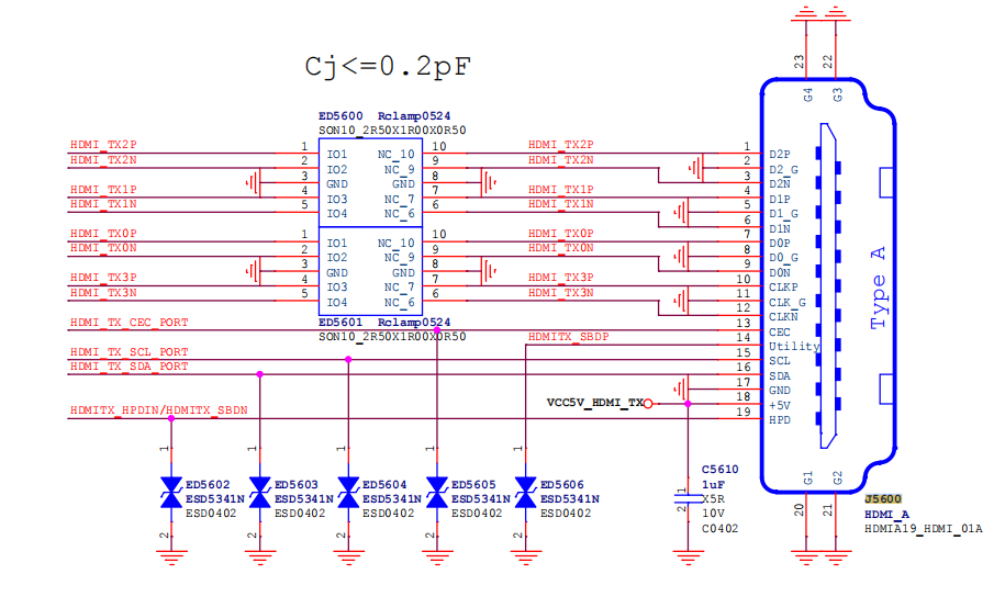
10. HDMI output 2
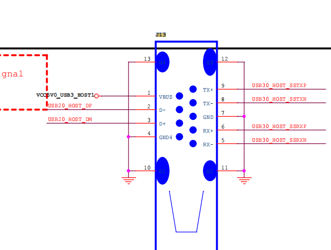
11. USB2.0/3.0
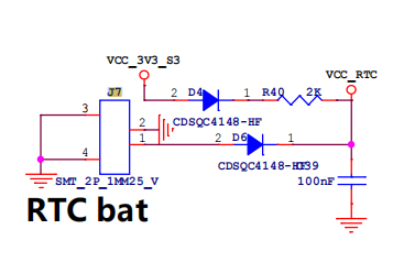
12. RTC interface
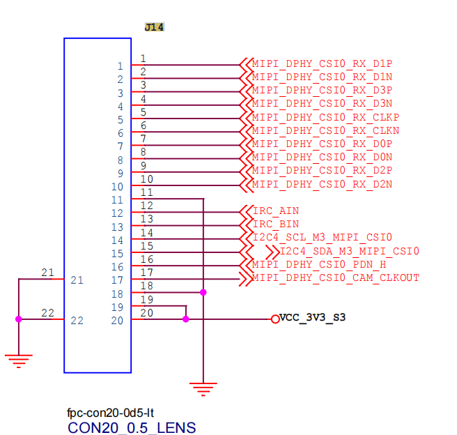
13. MIPI interface
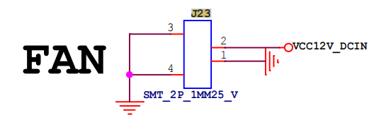
14. FAN interface
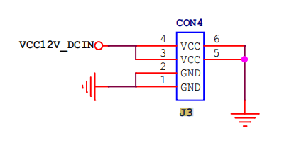
15. VCC12V_DCIN
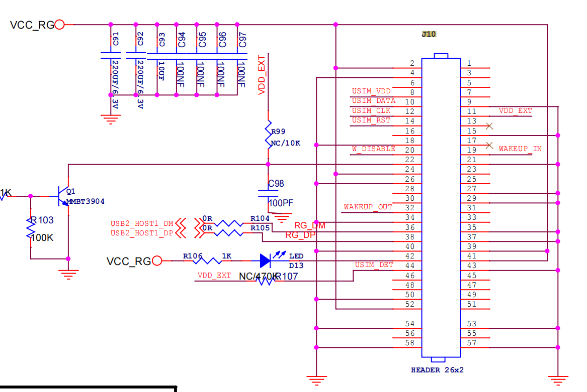
16. 4G module interface
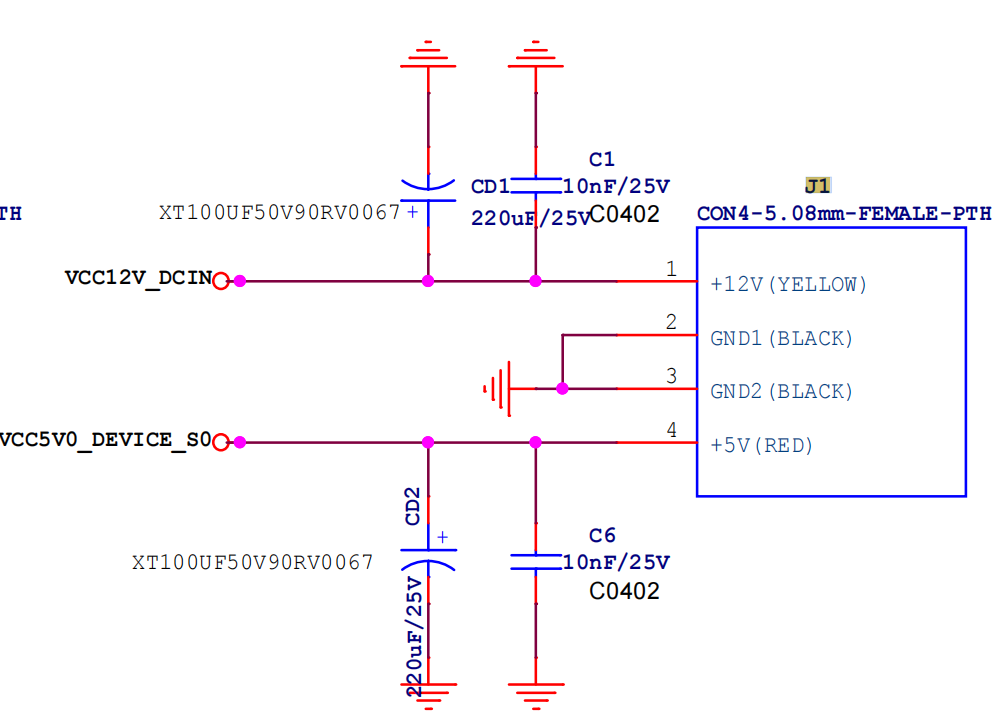
17. Hard disk power interface
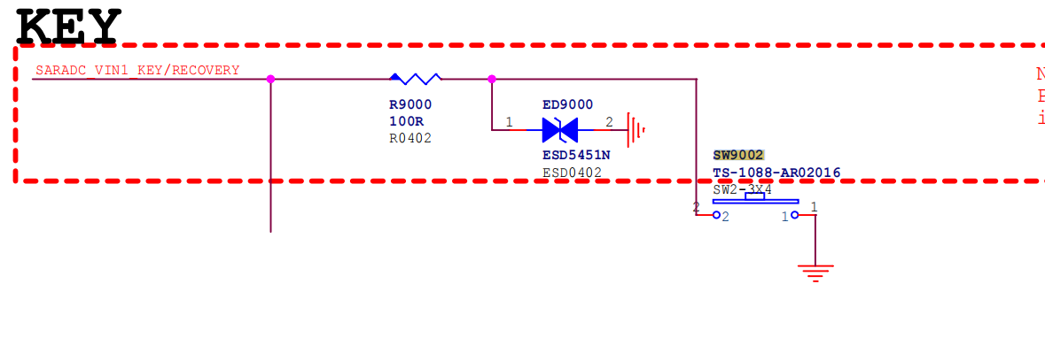
18. VIN1_KEY/RECOVERY
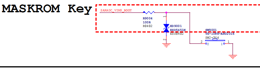
19. VIN0_BOOT
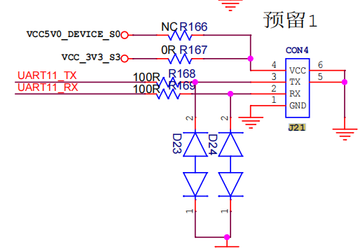
20. UART11 reserved port
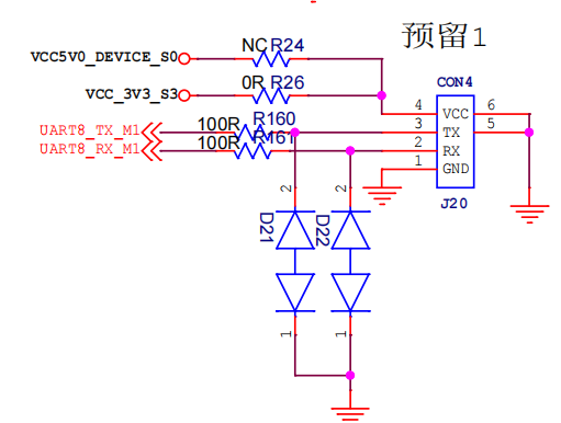
21. UART8 reserved port
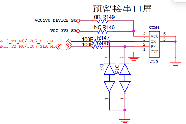
22. Reserved for serial screen
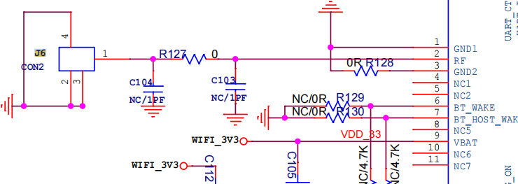
23. WiFi antenna interface
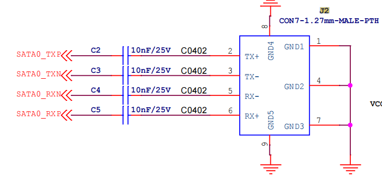
24. SATA data cable interface
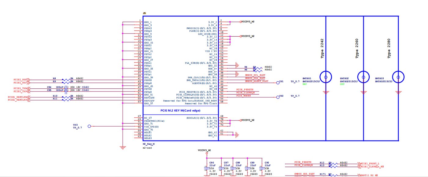
25. PCIE interface
IV. Common Device Questions and Answers
| Question | Answer |
|---|---|
| 1. | |
| 2. | |
| 3. |