100Channelwith TranscodingVideo EncoderUser Manual
Project: Device User Guide | page_id: 64
This manual applies to XST-800M100CH/P
RTSP to RTMP Video Encoder
Table of Contents
1 Device Introduction
2 User Interface
3 Status Display
4 ONVIF Device Discovery
5 PTZ Control
6 Multi-screen Live
7 Recording Playback
8 Channel Settings
9 System Settings
10 Device HLS Video Stream Output
1. Device Introduction
An RTSP-RTMP bidirectional conversion video encoder, which can be used for RTSP-to-RTMP streaming. It is a multi-function video encoder for a wide range of scenarios.
First Use
Use the Device Search Assistant to search for and modify the device IP. The device default IP is 192.168.0.15.
1. User Interface
This device is configured through a web management interface and can be managed and set up from PCs, tablets, mobile phones and other terminals. On a PC, Google Chrome is recommended for device management.

The default factory IP address of this device is 192.168.0.15. After changing the device IP with our dedicated Device Search Assistant software (see the Device Search Assistant manual for instructions), enter the device IP address in Google Chrome to access the device management login page, as shown below:
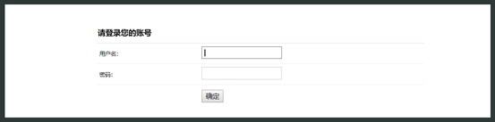
Figure 1
Enter the username and password. Initial default username: admin, password: admin. Click OK to enter the device configuration page. The device configuration page is divided into two windows: the left one is the function settings window and the right one is the function content window, as shown below:

Figure 2
1. Status Display
The home page of the configuration page shows the device operating status, as shown below:
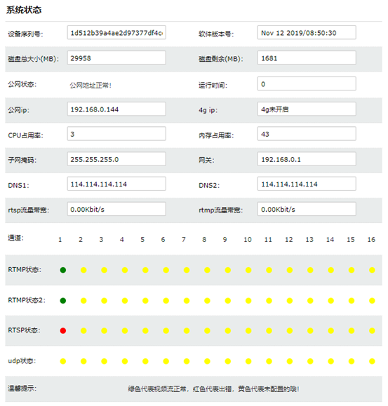
Figure 3
Note: rtsp traffic must not exceed the maximum hardware capability!!!
CPU usage must not exceed 90%.
2.1 Interface Introduction
The status display function shows the current operating status of the system, including software version, network information, rtsp/rtmp real-time bandwidth information, uptime, CPU and memory usage, and channel running status.
2.2 Channel Running Status Indicator Introduction
On the running status page you can view the running status of all channels. There are three colors.

Green: normal.

Yellow: not configured.

Red: error.
2.3. ONVIF Device Discovery
This device is compatible with all IPC cameras that support the ONVIF protocol. Click ONVIF Device Discovery on the left and the device lists the ONVIF-compatible IPC devices on the same LAN segment, as shown below:
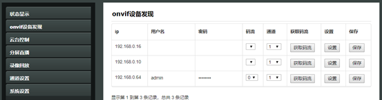
Figure 4
3. Obtaining the RTSP Stream from an IP Camera
In the ONVIF device discovery list, select the IPC you want to add, enter the IPC username and password, and click "Get Stream". After the stream is obtained successfully, the stream number of the IPC is displayed in the stream drop-down window of that IPC, such as 0, 1, 2, etc. Most IPCs support multi-stream output; usually the main stream number is stream 0 and the sub stream number is stream 1. Generally we select the main stream, i.e. stream 0.
As shown in the figure:
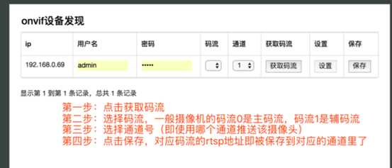
Figure 5
4. Channel Number Setting
After selecting the stream number, you need to select the channel number corresponding to that stream, i.e. which channel is used to push the IPC stream. After the selection is complete, click the Save button and the RTSP address of the corresponding stream is saved to the corresponding channel and used by that channel.
5. PTZ Control
This device is compatible with all PTZ controls that support the ONVIF protocol; it can be used to control PTZ IPC cameras. Select the corresponding channel number to control the IPC camera corresponding to that channel number, as shown below:
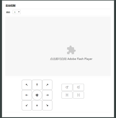
Figure 6
6. Multi-screen Live
The multi-screen live function supports simultaneous live streaming of multiple channels; 4-screen, 9-screen and 16-screen layouts can be selected. Multi-screen live displays channels in channel number order, starting from channel 1; when one page is not enough, they are arranged on the following pages automatically, and you can use the paging buttons below to go to the corresponding page.
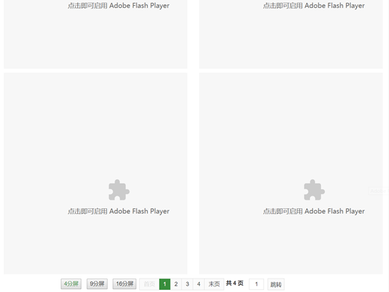
Figure 7
7. Recording Playback
The recording playback function requires local storage, such as an SD card or hard disk, and is supported on some models only. This function supports video stream storage, playback and video download.

By selecting the date and channel number, you can play back the video of the specified date and channel (the video must already be stored). Recording download supports downloading the video of any time range within the 24 hours of the selected date. Simply select the start time and end time below and click "Start Download" to download the recording to your local computer for storage and playback.
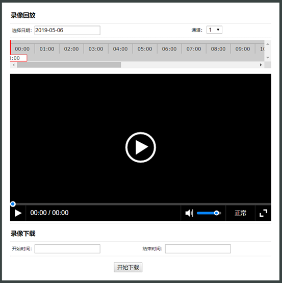
Figure 8
8. Channel Settings
Channel settings are used to configure the RTSP/RTMP streaming and pull streaming addresses of a specific channel, whether recording is enabled, and other functions. Taking channel 1 as an example, the RTSP-to-RTMP streaming configuration is described below.
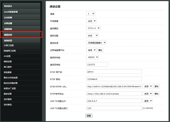
Figure 9
8.1 Channel Number Selection
The channel drop-down list is used to select the channel number to be configured. Depending on the model, the supported channel count is 16, 20, 40, 100, etc.
Enable recording is used to set whether the recording storage function of this channel is enabled.
Audio encoding is used to select the audio encoding method in the RTSP video stream; G711-U/G711-A/ACC can be selected. The correct encoding format must be selected for streaming to work properly. (Note: the 16-channel video encoder supports only RTSP streams with audio encoding G711-U/G711-A; 20-channel and above encoders support all three audio encoding methods.)
Audio setting switch is used to enable or disable audio. If the RTSP video stream has no audio, the audio setting must be disabled.
Audio source is used to set the audio source; network encoding camera and local analog audio can be selected. If the network encoding camera has no audio but you want the streamed video to carry audio, you can select local analog audio as the audio source.
The audio sampling rate must be set to the same value as the audio sampling rate of the RTSP video source for streaming to work properly. For the audio baud rate, the default setting is recommended.
    Note: before enabling audio, check the two audio parameters of the network camera:
1: Encoding method, currently supported: G711-A/G711-U/AAC
2: Sampling rate, 8000/16000/32000/44100/48000, etc.
Once the audio parameters are confirmed, fill in the corresponding parameters on the video encoder.
8.2 RTSP Username and Password:
Enter the username and password of the RTSP stream address. For an IPC video stream, enter the IPC username and password.
8.3 RTSP/RTMP URL:
If you use the RTSP-to-RTMP function, this address is the RTSP address obtained by ONVIF device discovery and does not need to be changed. Some network cameras have compatibility issues with the ONVIF protocol; if the device cannot be found or the stream cannot be obtained, you can enter the RTSP address of the network camera manually. Before entering the RTSP address manually, first verify with a player such as VLC that the RTSP video stream plays normally.
For the RTSP address rules of Hikvision and Dahua, see: docs.html
8.4 XSTRIVE Live Platform:
All our video encoders support the XSTRIVE live platform. Users must register on the XSTRIVE platform and bind the device before it can be used. Platform registration address: platform.xstrive.com, invitation code: xstrive. Platform documentation: docs.html
8.5 RTMP Publish Address:
The address used for RTMP streaming; refer to the streaming address in the streaming platform backend. It is recommended to copy the streaming address directly from the platform.
8.6 UDP TS Stream Output IP/Port:
Used to set the output IP and port of the UDP TS stream.
8.7 Transcoding Configuration Example:
Setting up 16-channel 1080P transcoding:
1. Set the video source addresses of channels 1~16 to the corresponding video source addresses to be transcoded.
2. Set compatibility mode to enabled.
Since each video stream to be transcoded can be transcoded into 2 streams:
Channels 17~32 correspond to the first stream of video sources 1~16, max resolution 1920x1080P
Channels 33~48 correspond to the second stream of video sources 1~16, max resolution 640x480P
RTMP to RTSP Configuration
After the two steps above, both the RTSP-to-RTMP function of 0.15 and the RTMP-to-RTSP function of 0.16 are configured. 0.15 converts the RTSP stream of the IPC camera into RTMP and pushes it to the 0.16 device; the 0.16 device receives the RTMP stream pushed by 0.15 and converts it into RTSP for RTSP pull streaming devices. 0.16 can output both RTMP and RTSP streams.

In the examples above we use channel 1 throughout. Channel 1 of 0.16 receives the RTMP stream pushed by channel 1 of 0.15 and outputs RTMP and RTSP streams at the same time. The RTMP stream address of 0.16 is rtmp://192.168.0.16/live/test and the RTSP stream address is rtsp://192.168.0.16/live/chn=0.
9. System Settings
System settings are used to configure device network information, system update, scheduled reboot and other functions.
9.1 Public Network Port Settings
Used to set the device IP address. You can choose DHCP or manually set the IP address according to your usage.
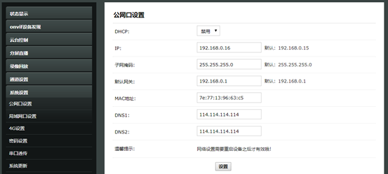
9.2 LAN Port Settings
This setting is available on dual-Ethernet devices only. The LAN port is used for intranet communication and the public network port for external communication.
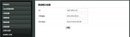
Note: for the LAN port, only the IP and subnet mask can be set; DNS, gateway, etc. cannot be set.
9.3 4G Settings
Supported on 4G models only; used to set the 4G Internet account and information.
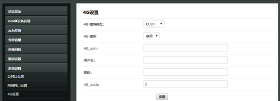
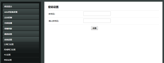
9.4 Password Settings
Set the management password for the user admin. The default password is admin; please remember the new password after changing it.
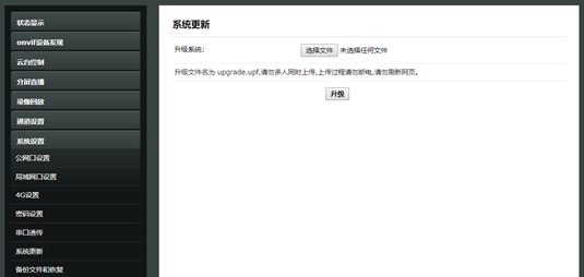
9.6 System Update
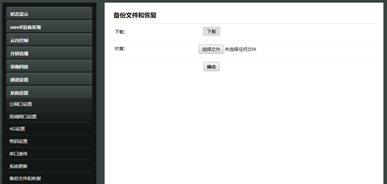
9.7 Backup Files and Restore
Used to back up and restore device configuration information; can be used for batch setup.
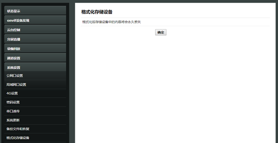
9.8 Format Storage Device
Used to format local storage. After formatting, the files stored on the device will be lost, so please operate with caution. Supported on storage models only.
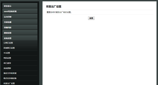
9.9 Restore Factory Settings
Used to restore the device to factory settings, including IP, default password, channel settings, etc. It is recommended to back up the existing settings before deleting them.
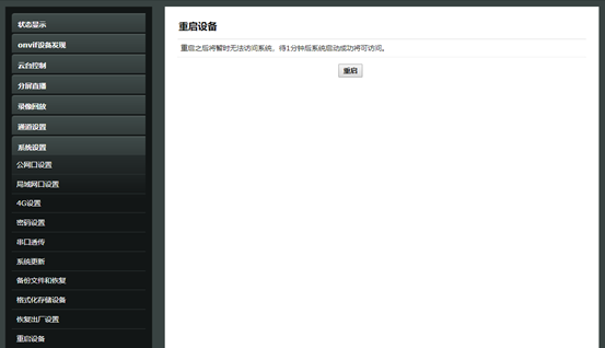
9.10 Reboot Device
Reboot the device manually.
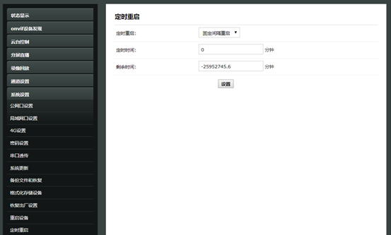
9.11 Scheduled Reboot
In some scenarios the device needs automatic maintenance. You can set the scheduled reboot period on the scheduled reboot page. You can choose daily reboot or automatic reboot at fixed intervals.

Note: the first time this item is set, the device reboots immediately (the remaining time is negative, which means the device is about to reboot).
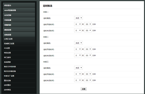
9.12 Scheduled Streaming
Set the device to stream during the configured time period. Currently six time periods are supported.

Streaming start time: sets when the video encoder starts streaming

Streaming end time: sets when the video encoder stops streaming
10 Playing the HLS Stream
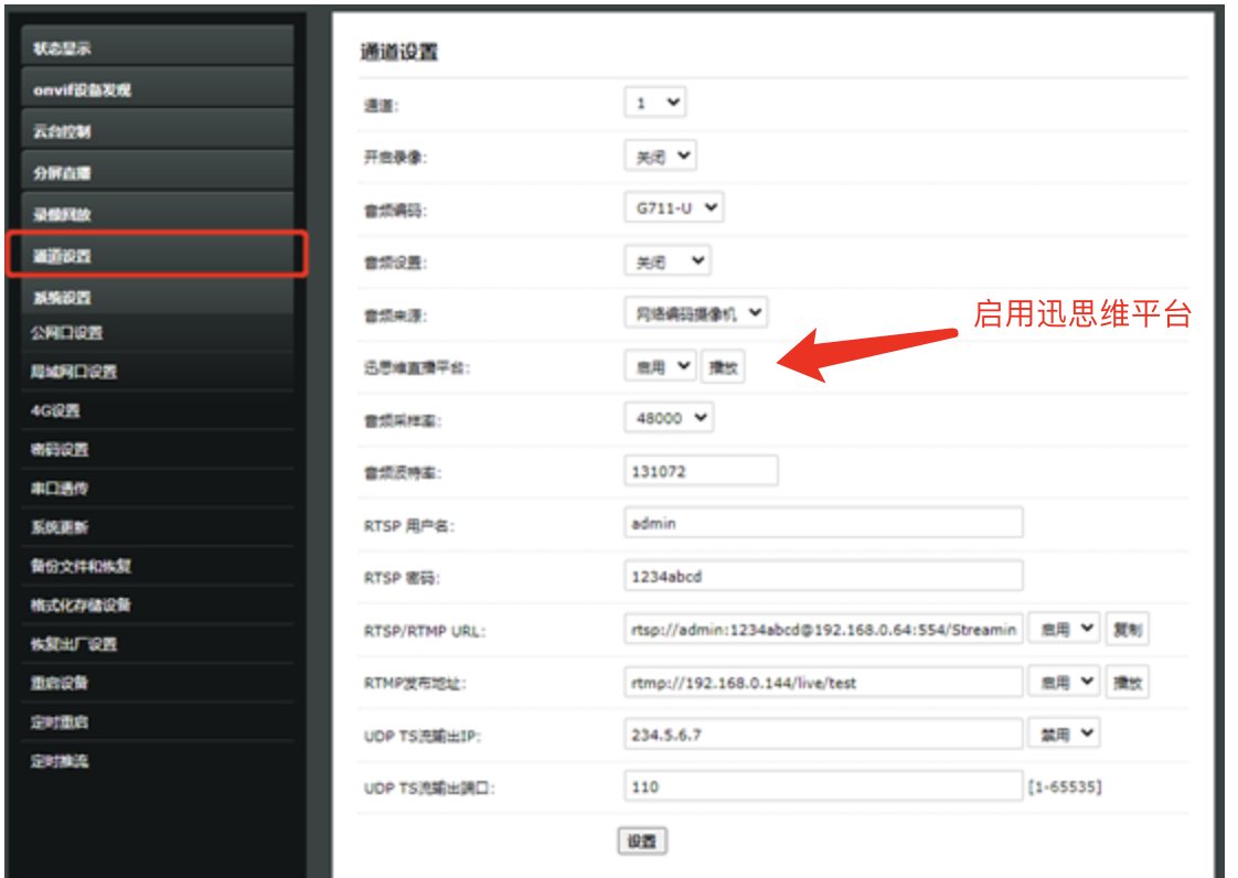
When the XSTRIVE platform is enabled for the selected channel:
1. The video of that channel can then output an HLS video stream. The HLS address rule is http://192.168.0.15/hlsram/live0/index.m3u8 (assuming the video encoder IP is 192.168.0.15)
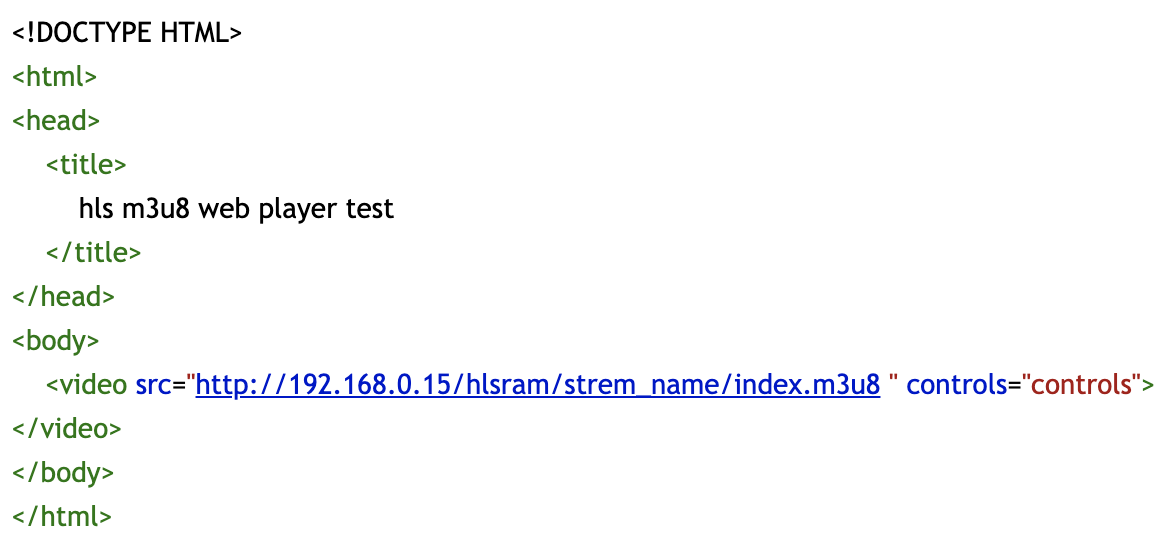
You can play this HLS address with VLC, or use the HTML code below to play it.