Targeted Playback Camera Manual
Project: Device User Guide | page_id: 864
[TOC]
1 Device Introduction
It directly outputs RTSP/RTMP video streams, works with NVR/DVR devices that support the ONVIF protocol, and can also push video streams directly to major live streaming platforms. Suitable for building remote monitoring platforms and for video live streaming applications.
Please use the search assistant to find the camera. The camera default IP is 192.168.0.10
2 Live Streaming and Recording Switching Function
There is a switch button on the camera. When pressed, the camera's live video switches to the recording from one hour ago and plays it in a loop (for example: if the button is pressed at 16:00, the video will loop through the local recording from 15:00 to 16:00). When the switch is released, it immediately switches back to the live video. As shown below
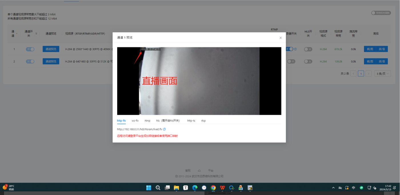
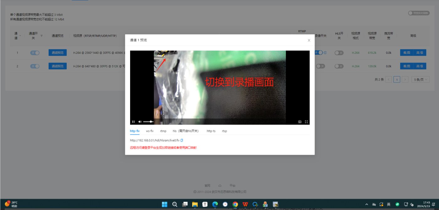
Notes:
- You need to wait for the device to connect to the network and complete time synchronization, and enable the recording switch
- When pressing the switch, make sure the device has local recording stored from one hour ago
- After a reboot, the switch state is also checked. If it is in the pressed state, the recording from one hour before the current time will be played; if it is not pressed, the current live picture will be played.
3、Web Configuration
Use the Device Search Assistant to search for and modify the device IP. Note that the computer and the device must be under the same switch/router. If it cannot be found, you can check the forced search option on the device search assistant.
Device search assistant download address: http://www.xstrive.com/download/
4、Login Page
This device is configured through a web management interface and supports management and configuration from PCs, tablets, mobile phones and other terminals. On PC, Google Chrome is recommended for device management.
You can use the dedicated device search assistant software mentioned above to change the device IP (see the device search assistant manual for instructions)
Enter the device IP address in Google Chrome to open the device management login page, as shown in Figure 1 below:
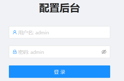
Figure 1
Enter the username and password. The initial default username is admin and the password is admin. Click OK to enter the device configuration page.
5、 Status Overview
The device configuration page is divided into two panes, the upper one being the function settings pane and the lower one the function content pane, as shown in Figure 2 below:
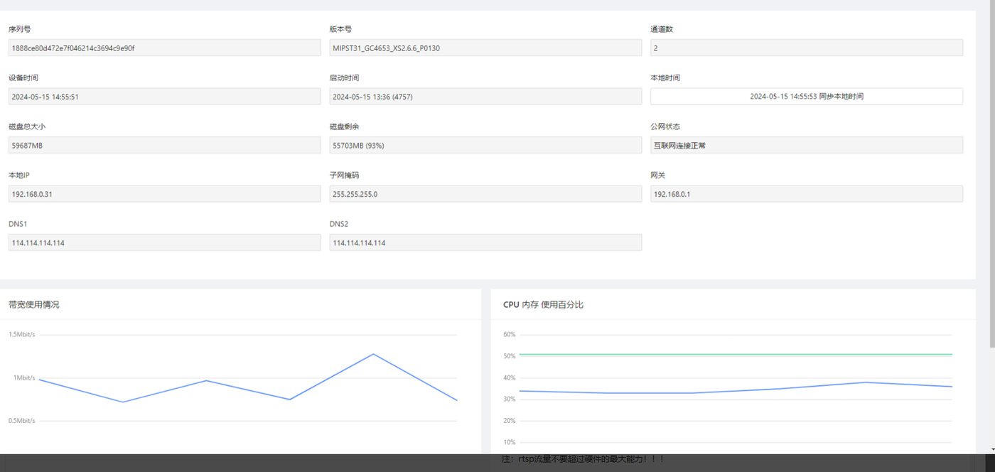
Figure 2
Status Overview: used to display the device running status, including the device serial number, software version, running time, Chinese/English switching, disk space (Note: the camera itself has no storage space; an SD card or hard disk must be installed for storage), device local IP, CPU and memory usage, and network information, etc.
After clicking the Sync PC Time button, the device time can be set to the time of the PC currently accessing it. The device time cannot be set manually.
Note: The RTSP traffic must not exceed the maximum hardware capability!!!
Note: The RTSP traffic must not exceed the maximum hardware capability!!!
CPU usage must not exceed 90%
6、 Channel Settings
This camera has 2 fixed channels and the channel switches are on by default
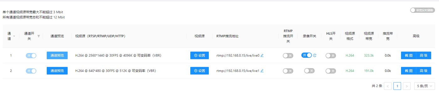
6.1 Channel Preview
Used to preview the real-time picture captured by the camera. Various video format addresses are shown below the video preview window, as shown in Figure 4 below:
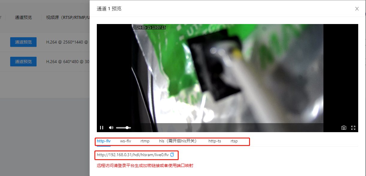
Figure 4
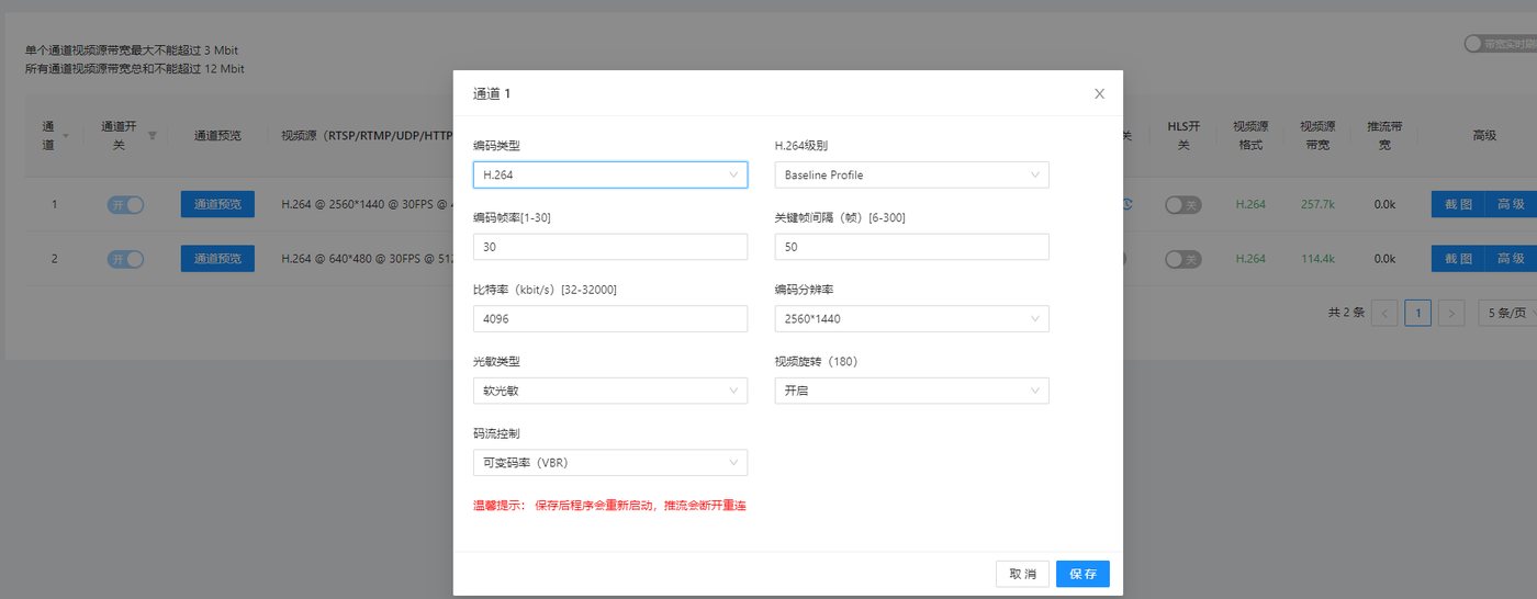
6.2 Basic Video Source Settings
The corresponding parameters within the range can be set manually as needed
6.3 RTMP Push Address
Used to set the RTMP push address. This address is provided by the RTMP streaming server. Please contact the streaming service provider to obtain it. (For example, to push streams to Douyin, you need the Douyin push address). After obtaining the push address, fill it in here
6.4 RTMP Push Switch
Used to enable or disable RTMP streaming
6.5 Recording Switch
Used to enable or disable recording of the video source (the recording function requires a hard disk to be installed)
6.6 HLS Switch
Used to determine whether to enable the HLS output function. The stream generation of the streaming platform also depends on this switch. For the streaming platform manual, please visit:
docs.html
6.7 Video Source Format
Used to display the encoding format of the video source, H.264 or H.265. Most platforms only support H.264 RTMP streaming. Please confirm with the streaming platform provider.
6.8 Pull Bandwidth
Used to display the bitrate bandwidth of the video source address
6.9 Push Bandwidth
Push bandwidth: used to display the bitrate bandwidth of RTMP streaming
6.10 Snapshot Configuration (supported by UI version 1.20.0.27 and later)
Used to set the snapshot switch, snapshot upload address and snapshot interval, etc. As shown in Figure 8 below:
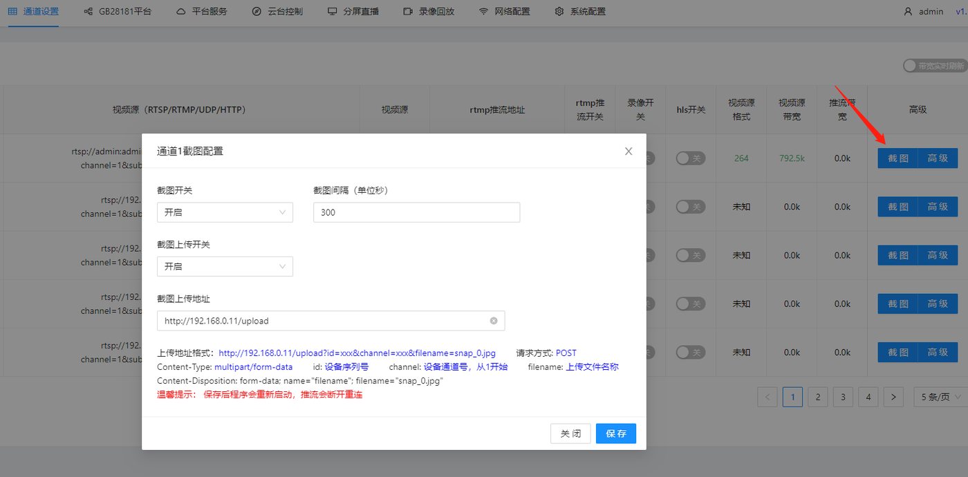
Figure 8
- Snapshot upload (if you need other formats or platform reception, please contact our business team for custom development)
Upload address format: http://192.168.0.11/upload?id=xxx&channel=xxx&filename=snap_0.jpg
Request method: POST
Content-Type: multipart/form-data
id: device serial number
channel: device channel number, starting from 1
filename: uploaded file name
Content-Disposition: form-data; name="filename"; filename="snap_0.jpg"
- Local snapshot access address format
http://192.168.0.11/tmp/snap_0.jpg
Replace 192.168.0.11 with your own device IP
snap_0 is the snapshot name of channel 1, snap_1 is the snapshot name of channel 2, and so on
- Remote snapshot access address format
http://serialnumber.cloud.xstrive.com:9502/tmp/snap_0.jpg

- Batch configuration API reference
doc-377.html
6.11 Advanced
The advanced settings are mainly used for: RTMP2 address and WebRTC video streaming, as well as camera audio related parameter settings. As shown below
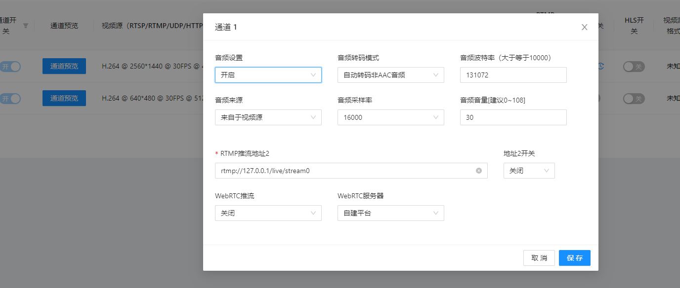
Figure 9
7、 Network Configuration
The basic configuration page is as follows: when DHCP is enabled, the router automatically assigns an IP to the device and the IP address is not fixed; when DHCP is disabled, you can set a fixed IP yourself
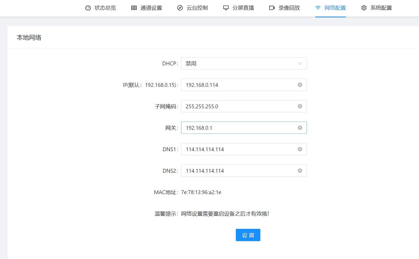
7.1 Advanced Network Configuration
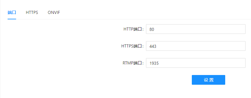
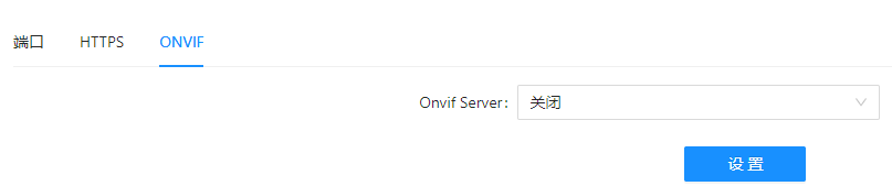
Used to set the camera port number and the ONVIF switch
8、 GB28181 Platform
GB28181 device management and service configuration is a server function of GB28181 and is only supported by our streaming server products. Video encoder devices only support the GB28181 platform access function: that is, registering the video in the channel as a GB28181 client to the GB28181 server.
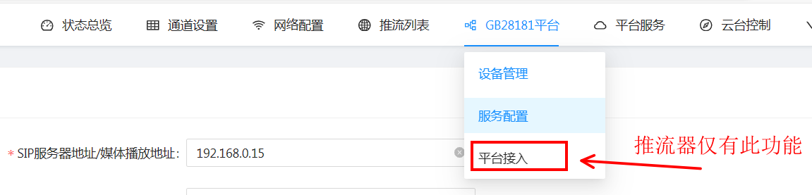
Figure 15
The configuration is obtained from the GB28181 server. Fill in the SIP service configuration parameters in the corresponding information fields, including the SIP server address, SIP transport protocol, SIP transport ID and SIP server domain, etc., as shown in Figure 16 below:
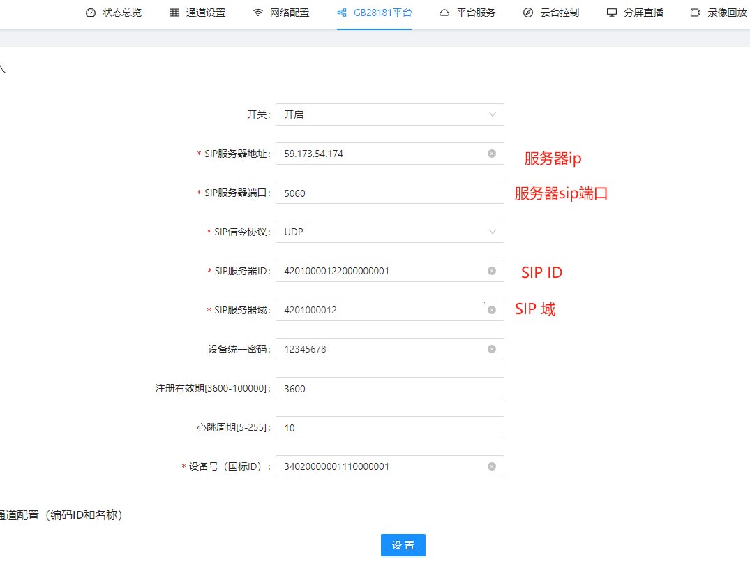
Figure 16
After successful registration, the registered video encoder device can be seen on the GB28181 server, as shown in Figure 17 below:

Figure 17
10、 PTZ Control
This device is compatible with all PTZ controls that support the ONVIF protocol, and can be used to control IPC cameras with a PTZ. Select the corresponding channel number to control the PTZ of the IPC camera corresponding to that channel, as shown in Figure 20 below:
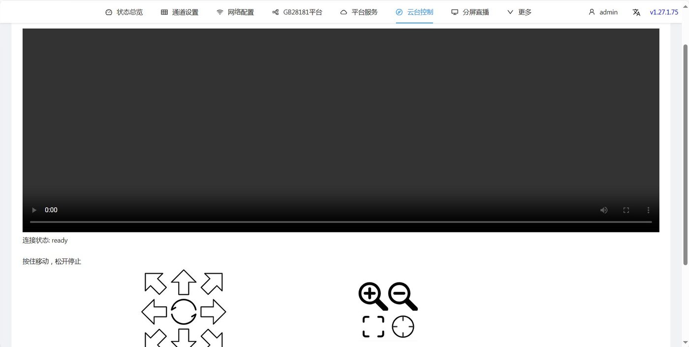
Figure 20
11、 Split-Screen Live Streaming
The split-screen live streaming function supports live streaming of multiple channels at the same time, and supports 4-screen, 9-screen and 16-screen settings. Move the mouse over the corresponding display area and a channel selection button will pop up. Click the channel selection button and select the channel to be displayed in that area. As shown in Figure 21 below:
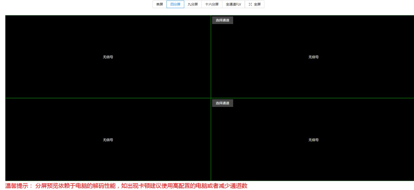
Figure 21
12、 Recording Playback
 The recording playback function requires local storage support, such as an SD card or hard disk. (Note: it is supported only on some models, and an SD card or hard disk must be installed separately). This function supports video stream storage, playback and video download.
 By selecting the date and channel number, you can play back the video of the specified date and channel (the video must have been stored). Recording download supports downloading video of any time range within the 24 hours of the selected date. Simply select the start time and end time below, then click Start Download to download the recording to your local device for saving and playback.
The downloaded recording format is a TS file
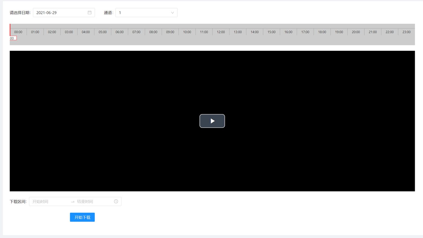
Figure 22
13、 VOD Management
VOD management requires local storage support and the device needs a hard disk installed. Click Add Upload to upload local audio and video files, and click the play link to generate a file playback link. In Channel Preview - Video File Search, you can set multiple video files for carousel, as shown in Figure 23 below:
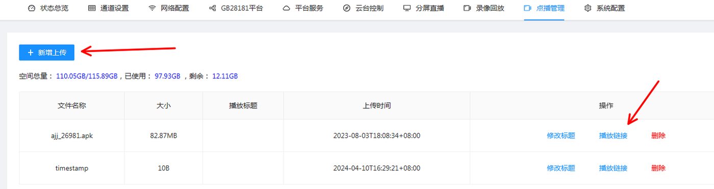
Figure 23
14 System Configuration
System settings are used to configure device password modification, image settings, serial port passthrough, GPS file download, system upgrade, formatting, scheduled reboot, API authentication, scheduled streaming, etc. As shown in Figure 24 below:
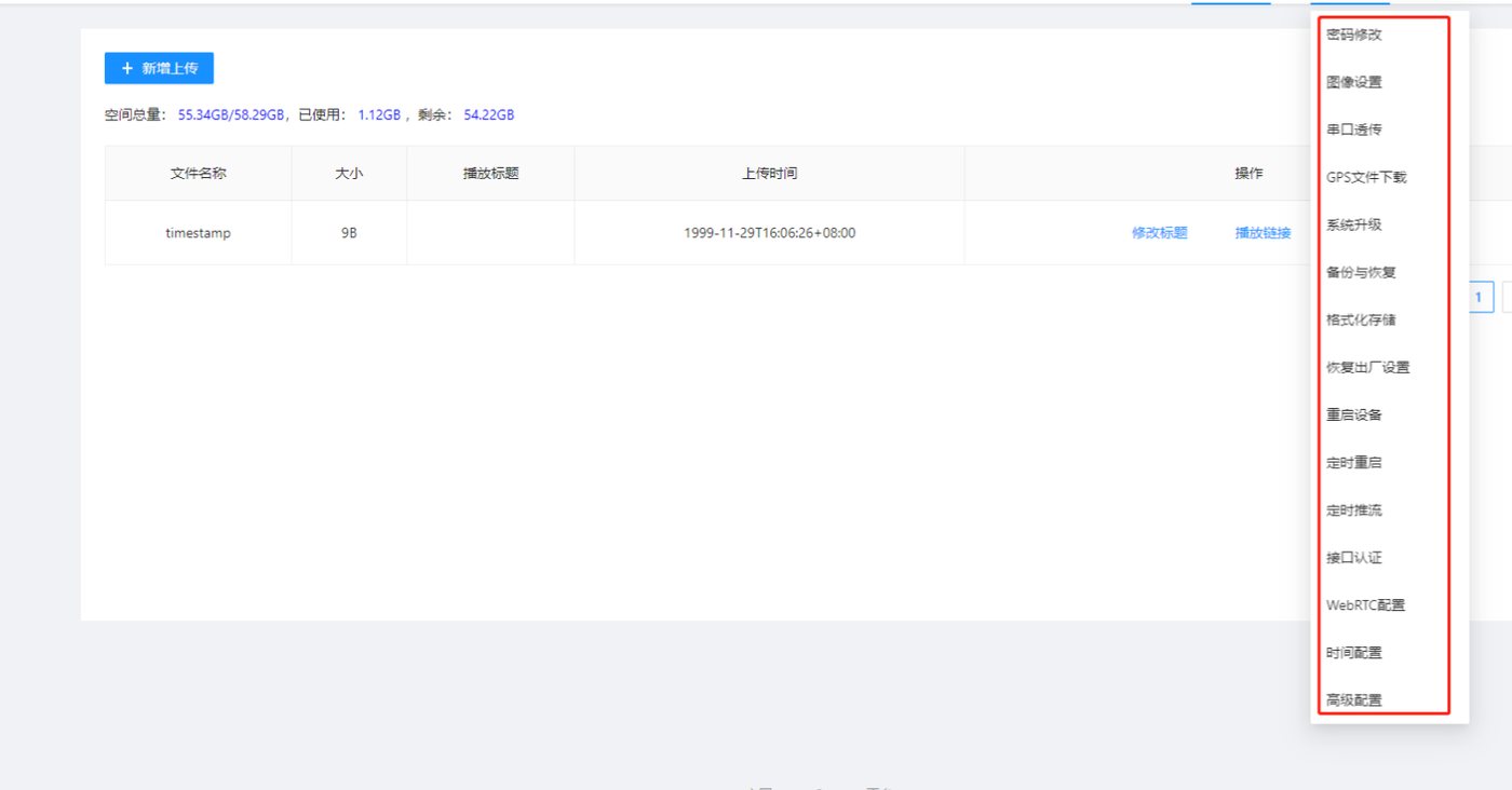
Figure 24
14.1 Password Modification
Set the management password for the username admin. The default password is admin. Please remember the new password after changing it. As shown in Figure 25 below:
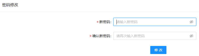
Figure 25
14.2 Image Settings
Camera image parameter adjustment
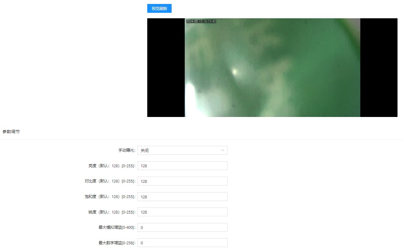
14.2 Serial Port Passthrough
Only for models with a serial port. Currently only TCP client mode is supported. As shown in Figure 26 below:
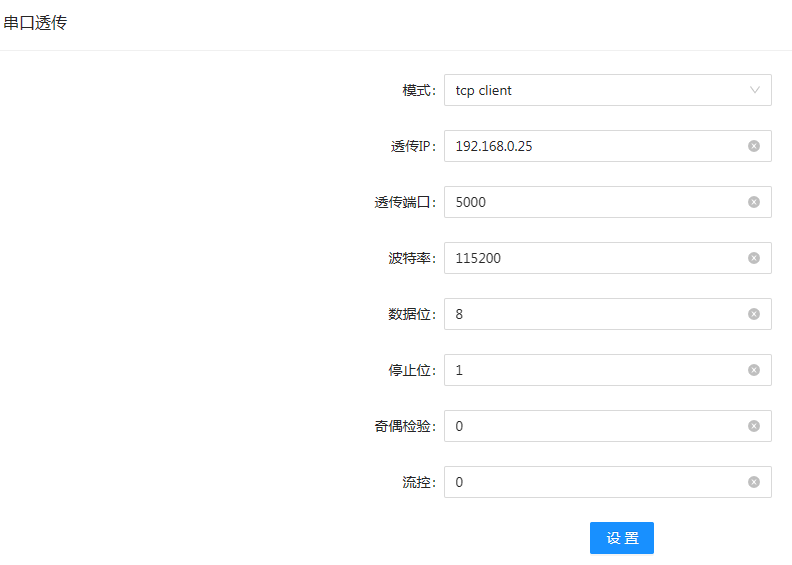
Figure 26
14.3 System Upgrade
Used for network software upgrades. (Note: all our devices have a one-year warranty. Upgrades are free within the warranty period, and upgrades are not supported after one year), as shown in Figure 27 below:
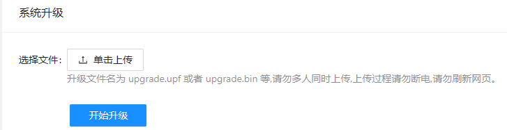
Figure 27
14.4 Backup and Restore
Used to back up and restore the device configuration information, which can be used for batch configuration, as shown in Figure 28 below:
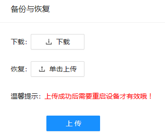
Figure 28
17.5 Format Storage
Used to format the local storage. Files stored on the device will be lost after formatting, so please operate with caution. Only supported on models with storage, as shown in Figure 29 below:
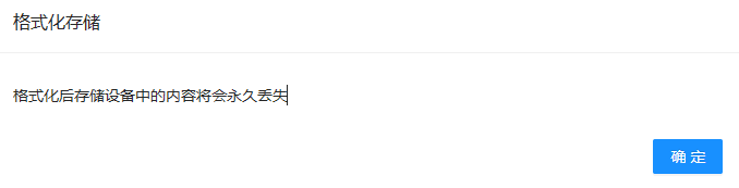
Figure 29
14.6 Restore Factory Settings
Used to restore the device factory settings, including IP, default password, channel settings, etc. It is recommended to back up the current settings before restoring. As shown in Figure 30 below:
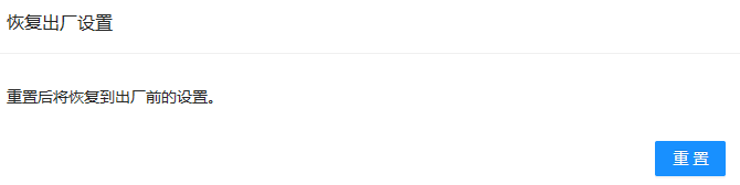
Figure 30
14.7 Reboot Device
Used to manually reboot the device. As shown in Figure 31 below:
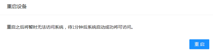
Figure 31
14.8 Scheduled Reboot
In some scenarios the device needs automatic maintenance. You can set the scheduled reboot period on the scheduled reboot page. You can choose daily reboot or automatic reboot at a fixed interval. As shown in Figure 32 below:
Daily reboot:
  When this option is selected, the remaining time and scheduled time parameters below can be ignored. The device will reboot at 03:00 every day.
Fixed interval reboot
  When this option is selected, you need to set the scheduled time parameter in minutes. For example, if it is set to 60, the device will reboot every 60 minutes. The remaining time below means how much time is left before the next reboot. A negative value means the device will reboot immediately.
Note: When this item is set for the first time, the device will reboot immediately. (A negative remaining time means the device is about to reboot):
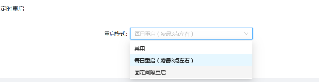
Figure 32
14.9 Scheduled Streaming
Set the device to stream during the configured time period. Currently six time periods are supported. As shown in Figure 33 below:
Streaming start time: sets the time when the video encoder starts streaming
Streaming end time: sets the time when the video encoder stops streaming
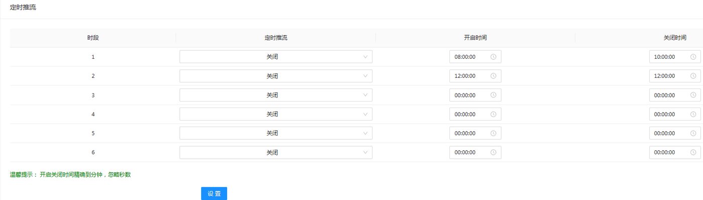
Figure 33
14.10 API Authentication
Mainly for customers who need platform integration. All our devices provide HTTP API integration. For details, refer to the API documentation: doc-258.html
(Note: for API integration we only provide integration documentation, and customers need to implement it themselves according to the documentation. If you need us to provide integration services, a separate fee is required)
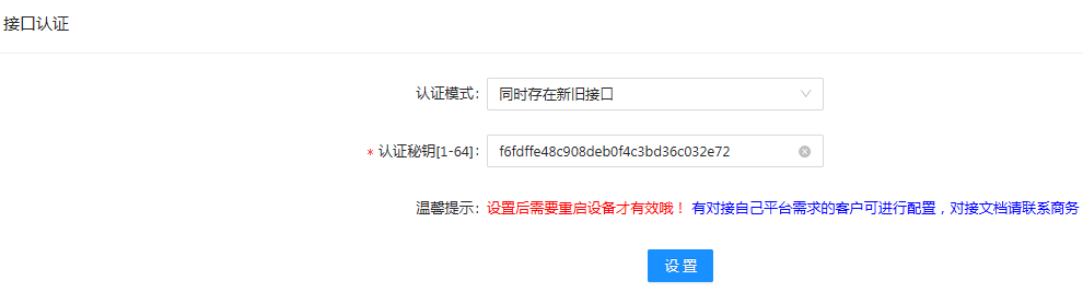
Figure 34
14.11 WEBRTC Configuration
Only some video encoder products support WebRTC streaming, and cameras need to purchase the WebRTC configuration. For details, please consult customer service
Customers who need to forward video streams to a server through the WebRTC protocol can configure it on this page. For detailed configuration methods, refer to: docs.html
Currently only self-built platforms, Tencent Cloud TRTC, Tencent Cloud LEB, srs and zlmediakit are supported. To support other platforms, please contact us for customization. The push address, playback address and secret key must be provided by the target WebRTC server
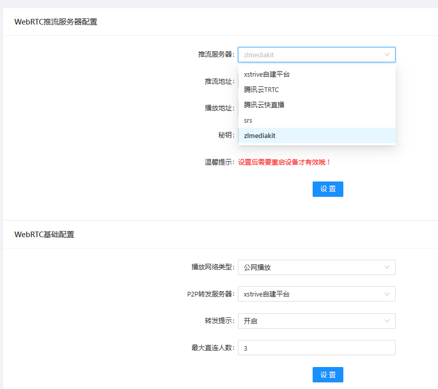
Figure 35
14.12 Time Configuration
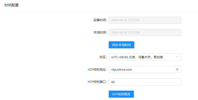
Figure 36
14.13 Advanced Configuration
Used to set the device name and to enable or disable the device login page. When enabled, the device password must be entered each time you log in to the device; when disabled, you can directly enter the device backend without a password
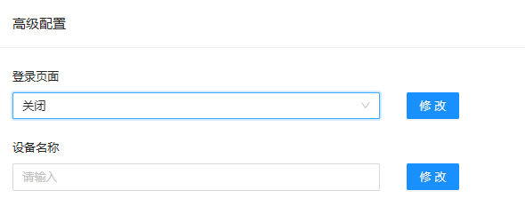
Figure 3