CameraGeneral Guide
Project: Device User Guide | page_id: 1621
[TOC]
This manual applies to our pusher, streaming media server and camera devices
Note: since this manual is a generic version, the screenshots in the manual may differ from the actual pages of the specific device. Please refer to the actual device pages.
Contents
1 Packing List
2 Product Application
3 Device Introduction
4 Quick LAN Playback Address
5 First Use
6 Login Interface
7 Status Overview
8. Channel Settings
10. GB28181 Platform
12. PTZ Control
13. Split-Screen Live Streaming
14. Recording Playback
16. System Configuration
18. User Center (only supported by streaming media server devices above S40)
20. Remote Video Playback
21. Remote Management of LAN Devices
22. Description of IP Addresses in 4G Mode and WiFi Mode
23. https Address Playback
24. Product Return and Exchange Instructions
1. Packing List
Device x1, power supply x1, user manual x1 (Note: all products only provide an electronic version of the user manual)
2. Product Application
- Multi-platform live streaming push 2. Unified management of network surveillance video 3. Network video protocol conversion 4. GB-28181 public security network 5. ONVIF device search and management 6. Centralized management of PTZ cameras 7. Kindergarten live video streaming 8. LAN live video streaming 9. Transparent kitchen and construction site live streaming, etc.
3. Device Introduction
This device is an RTSP/RTMP/HTTP-FLV/UDP-TS/HLS multi-protocol conversion and streaming device developed and manufactured by our company. It can be used for RTMP push and is a multi-function, multi-scenario video streaming device.
Supported input and output video formats: RTSP/RTMP/RTP/HTTP-FLV/UDP-TS/HLS
4. First Use
Use Device Search Assistant to search for and modify the device IP. Note that the computer and the device must be under the same switch/router. If the device cannot be found, you can check the forced search option on the Device Search Assistant.
Device Search Assistant download address: http://www.xstrive.com/download/
5. Login Interface
This device uses a web management interface for configuration, and supports management and setting of the device from PCs, tablets, mobile phones and other terminals. On the PC side, it is recommended to use the Google browser to manage the device.

After changing the device IP using the dedicated Device Search Assistant software of our company (see the Device Search Assistant manual for the modification instructions)
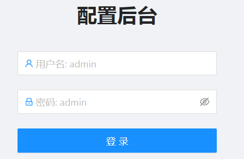
Enter the device IP address in the Google browser to enter the device management login interface, as shown in Figure 1 below:
6. Quick LAN Playback Address:
Channel 1 http://192.168.0.15/open/live-play/?a=1
Channel 2 http://192.168.0.15/open/live-play/?a=2
Channel 3 http://192.168.0.15/open/live-play/?a=3
...The IP needs to be changed to your own device IP. a=1 means channel 1, a=2 means channel 2, and so on
7. Status Overview
The device configuration interface is divided into upper and lower windows. The upper one is the function setting window, and the lower part is the function content window, as shown in Figure 2 below:
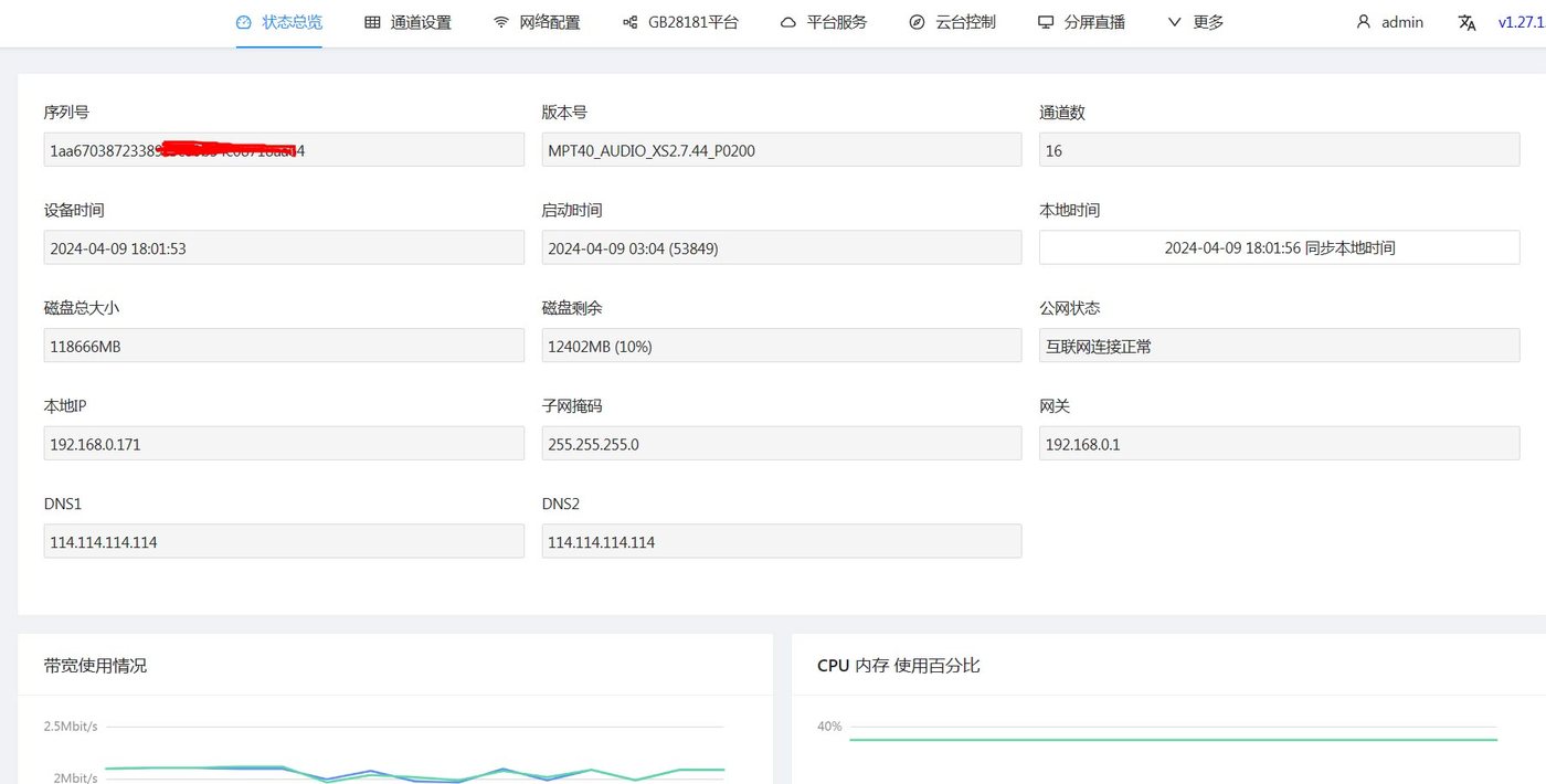
Figure 2
Status overview: used to display the device running status, including the device serial number, software version number, running time, Chinese/English switching, disk space (Note: the pusher itself has no storage space, and an SD card or hard disk needs to be installed for storage), device local IP, CPU and memory usage, and network information, etc.
After clicking the Sync Computer Time button, the device time can be set to the time of the currently accessing computer. The device time cannot be set manually.
Note: the rtsp traffic must not exceed the maximum capability of the hardware!!!
CPU usage must not be higher than 90%
8. Channel Settings
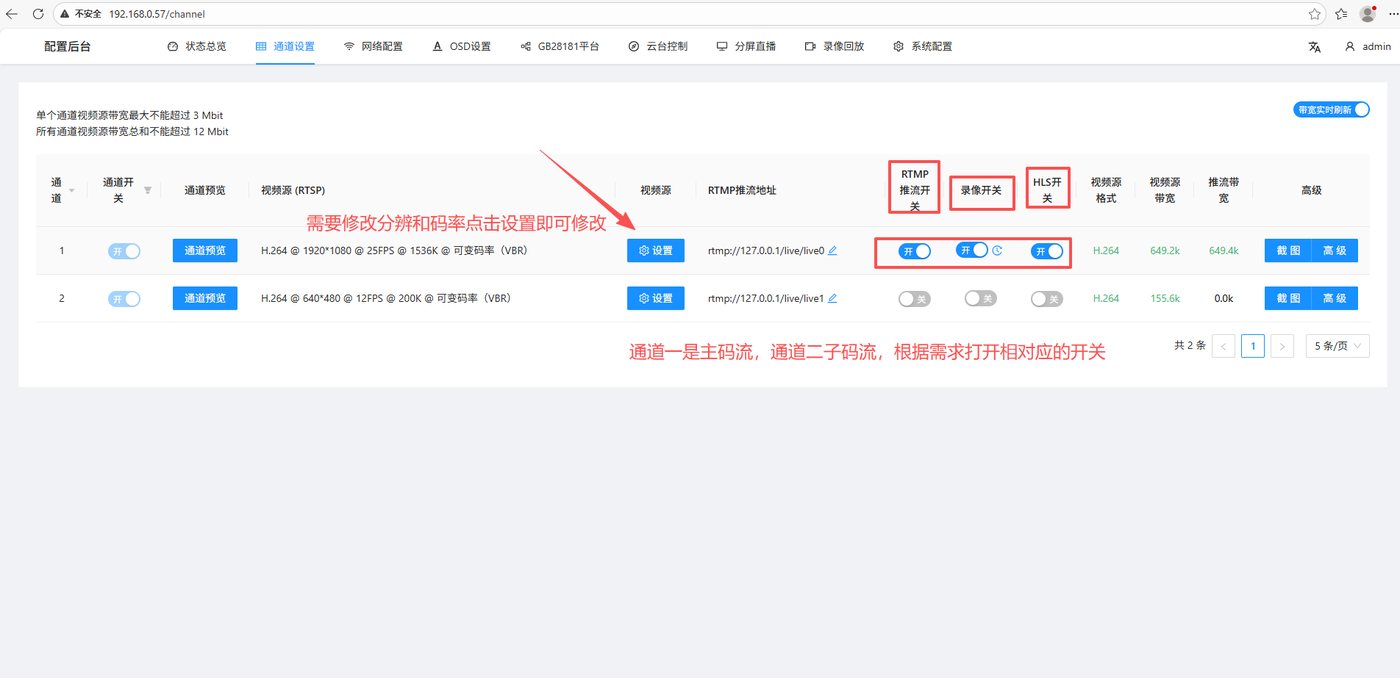
You can configure the device bitrate, frame rate, resolution and other information
8.5 RTMP Push Address
Used to set the rtmp push address. This address is provided by the rtmp streaming media server, please contact the streaming media service provider to obtain it. (For example, to push streams to Douyin, you need the push address of Douyin). After obtaining the push address, fill in the push address here
8.6 RTMP Push Switch
Used to control the enabling and disabling of rtmp push
8.7 Recording Switch
Used to control the enabling and disabling of recording of the video source (the recording function requires an additional hard disk)
8.8 HLS Switch
Used to determine whether to enable the HLS output function. At the same time, the video stream generation of the streaming media platform also depends on this switch. For the streaming media platform manual, please visit:
docs.html
8.9 Video Source Format
Used to display the encoding format of the video source, H.264 or H.265. Most platforms only support H.264 rtmp push; please verify this with your streaming media platform supplier.
8.12 Snapshot Configuration (supported from UI version 1.20.0.27)
Used to set the snapshot switch, snapshot upload address and snapshot time interval, etc., as shown in Figure 8 below:
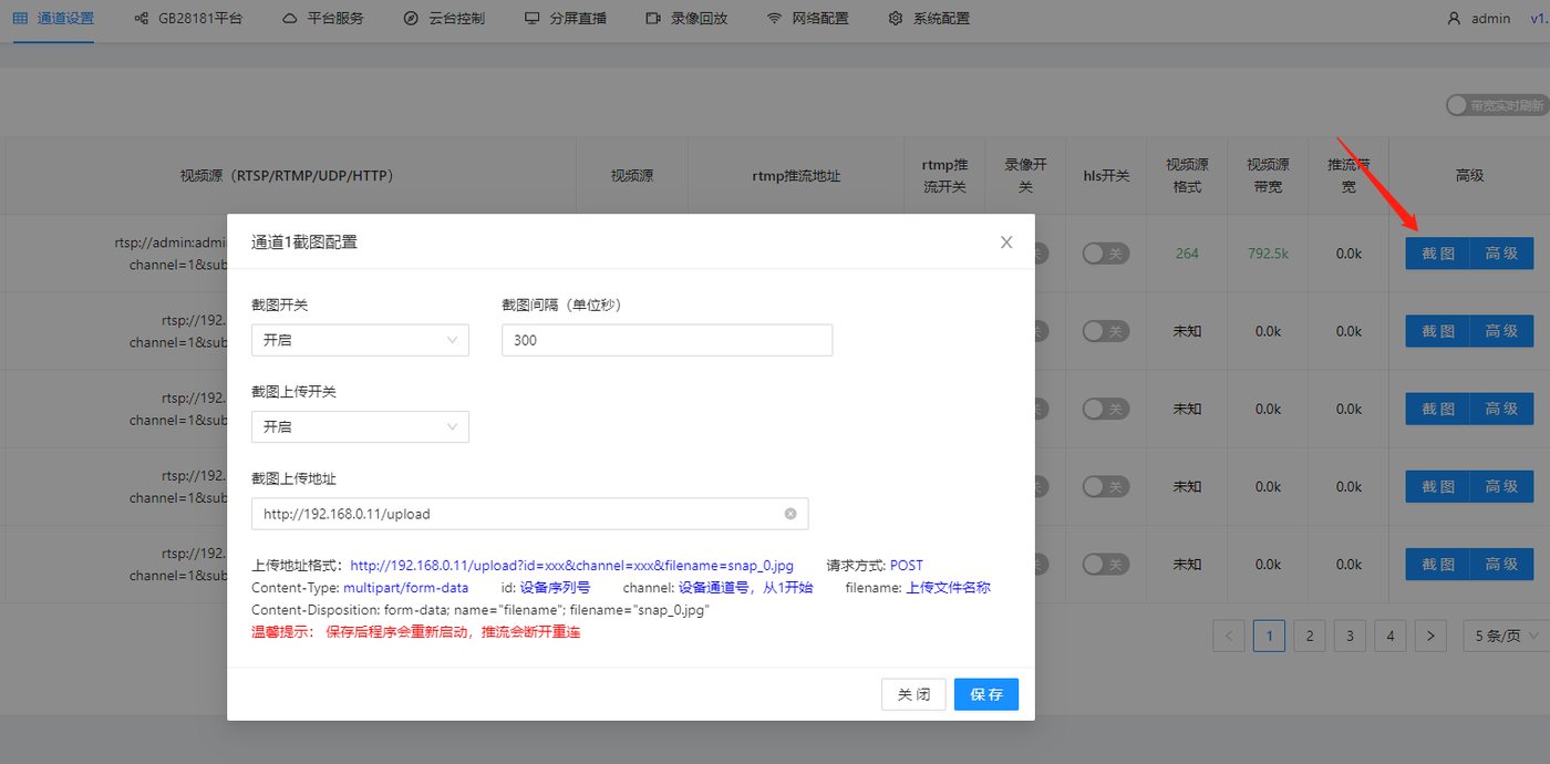
Figure 8
- Snapshot upload (if you need other formats or platform reception, please contact sales for custom development)
Upload address format: http://192.168.0.11/upload?id=xxx&channel=xxx&filename=snap_0.jpg
Request method: POST
Content-Type: multipart/form-data
id: device serial number
channel: device channel number, starting from 1
filename: uploaded file name
Content-Disposition: form-data; name="filename"; filename="snap_0.jpg"
- Local access snapshot address format
http://192.168.0.11/tmp/snap_0.jpg
Replace 192.168.0.11 with your own device IP
snap_0 is the snapshot name of channel 1, snap_1 is the snapshot name of channel 2, and so on
- Remote access snapshot address format
http://serial number.cloud.xstrive.com:9502/tmp/snap_0.jpg

- For the batch configuration interface, please refer to
doc-377.html
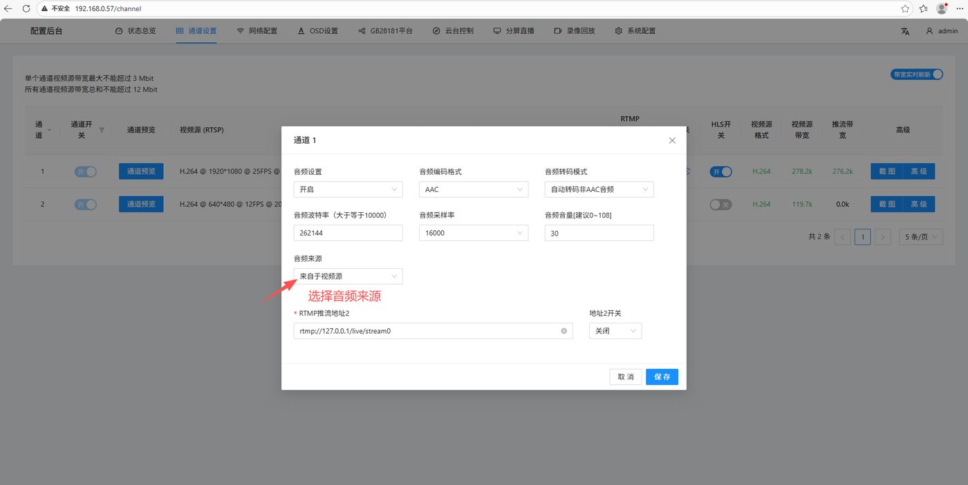
8.13 Advanced
Advanced: the advanced settings are used to configure the audio switch and source selection
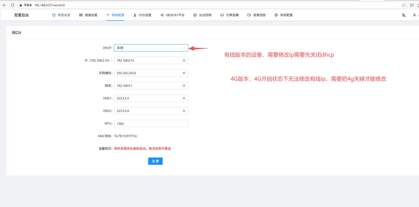
9. Network Configuration
The network settings are used to set the IP address of the device. Cameras generally have three modes: wired, WiFi and 4G
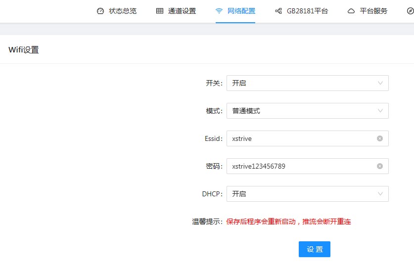
For devices that support WiFi, the configuration interface is as follows:
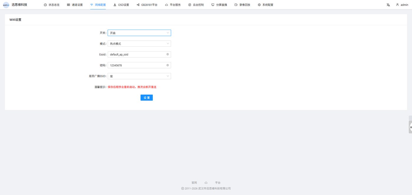
Hotspot mode: after the device enables hotspot mode, there will be a WiFi account and password. After the mobile phone connects to this WiFi, open the IP 192.168.11.1 in the mobile phone browser to access the device backend
10. GB28181 Platform
The GB28181 device management and service configuration is used as the GB28181 server function, which is only supported by our streaming media server products. The pusher device only supports the GB28181 platform access function: that is, registering the video in the channel as a GB28181 client to the GB28181 server.
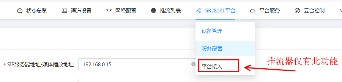
Figure 15
The configuration is obtained from the GB28181 server. Fill in the SIP service configuration parameters in the corresponding information column, including the SIP server address, SIP transport protocol, SIP transport ID and SIP server domain, etc., as shown in Figure 16 below:
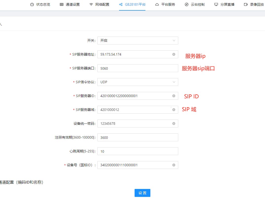
Figure 16
After the registration is successful, the registered GB28181 device can be seen on the GB28181 server, as shown in Figure 17 below:

The streaming media server can be used as a GB28181 service,
Figure 17
12. PTZ Control
PTZ control of the pusher / streaming media server
Compatible with all PTZ controls that support the Onvif protocol, it can be used to control IPC cameras with PTZ. Select the corresponding channel number to perform PTZ control on the IPC camera corresponding to the channel number, as shown in Figure 20 below:
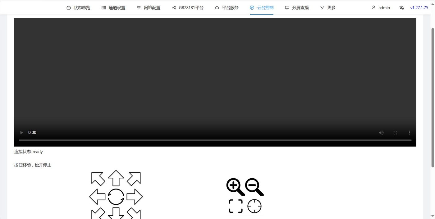
Figure 20
PTZ control of PTZ cameras
Click up, down, left and right directly to complete the PTZ control.
Cruise settings
  Step 1: set the cruise points and set presets 1-32, for example, set 8 presets: 1 2 3 4 5 6 7 8
  Step 2: call cruise line 1
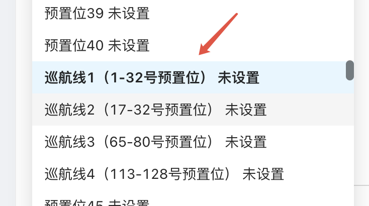
Step 3: to cancel cruising, select cruise line 1 and click Delete
13. Split-Screen Live Streaming
The split-screen live streaming function supports simultaneous live streaming of multiple channels. You can select 4-screen, 9-screen and 16-screen settings. Place the mouse in the corresponding display area, and the channel selection button will pop up. Click the channel selection button and select the channel to be displayed in this area, as shown in Figure 21 below:
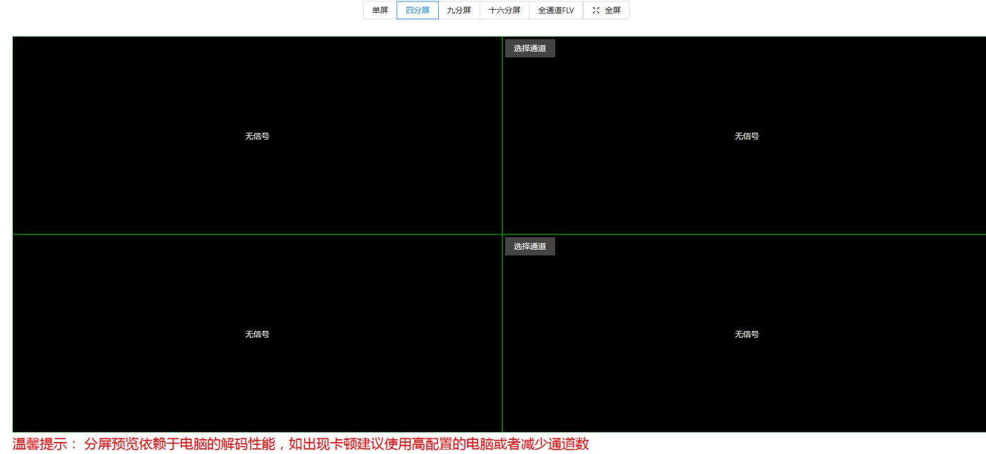
Figure 21
14. Recording Playback
The recording playback function requires local storage support, such as an SD card, hard disk, etc. (Note: only some models of devices support it, and an SD card or hard disk needs to be installed separately). This function supports video stream storage, playback and video download functions.

By selecting the date and channel number, you can play back the video of the specified date and specified channel number (the video must have been stored). Recording download supports the download of videos within any time period of the 24-hour time period of the selected date. Just select the start time and end time below, then click Start Download to download the recording to the local for saving and playback.
The downloaded recording format is a TS file
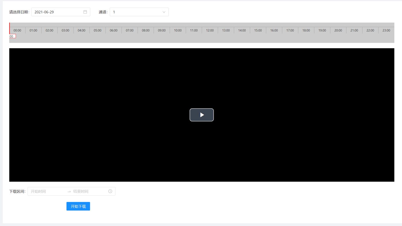
Figure 22
16. System Configuration
System settings are used to configure the device password modification, serial port passthrough, GPS file download, system upgrade, formatting, scheduled restart, interface authentication, scheduled push, etc. As shown in Figure 24 below:
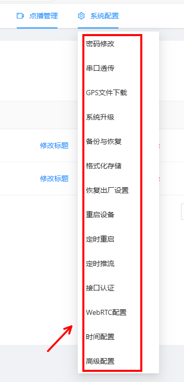
Figure 24
16.1 Password Modification
Set the management password of the user name admin. The default password is admin. Please remember the new password after modification, as shown in Figure 25 below:
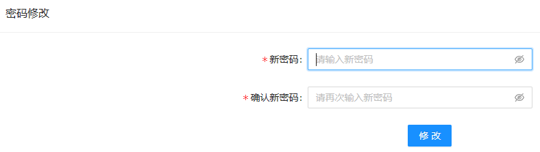
Figure 25
16.3 System Upgrade
Used for network software upgrade (Note: all our devices have a one-year warranty, and can be upgraded for free within the warranty period; upgrades are not supported after one year), as shown in Figure 27 below:
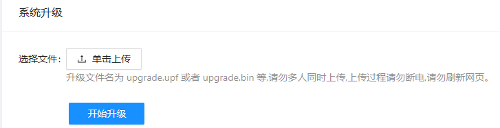
Figure 27
16.4 Backup and Restore
Used to back up and restore the device configuration information, which can be used for batch settings, as shown in Figure 28 below:
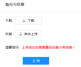
Figure 28
16.5 Format Storage
Used to format the local storage. After formatting, the files stored in the device will be lost, please operate with caution. Only models with storage are supported, as shown in Figure 29 below:
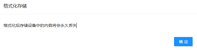
Figure 29
16.6 Restore Factory Settings
Used to restore the factory settings of the device, including IP, default password, channel settings, etc. It is recommended to back up the existing setting information before deleting it, as shown in Figure 30 below:
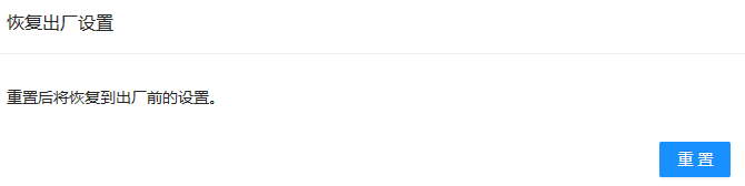
Figure 30
16.7 Restart Device
Used to manually restart the device, as shown in Figure 31 below:
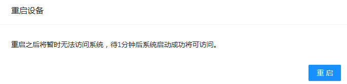
Figure 31
16.8 Scheduled Restart
In some occasions, the device needs automatic maintenance. The time period for the scheduled restart can be set on the scheduled restart interface. You can choose daily restart and automatic restart at fixed time intervals, as shown in Figure 32 below:
Daily restart:
  When this option is selected, you can ignore the remaining time and timing parameters below. The device will restart at 03:00 every day
Fixed interval restart
  When this option is selected, you need to set the timing parameter, the unit is minutes. For example, if it is set to 60, the device will restart every 60 minutes. The remaining time below means how much time is left before the next restart. A negative number means the device will restart immediately.
Note: when this item is set for the first time, the device will restart immediately. (A negative remaining time means the device is about to restart):
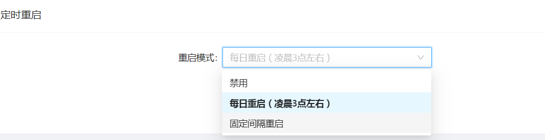
Figure 32
16.10 Interface Authentication
Mainly for customers who need to connect to a platform. All our devices provide http interfaces for connection. For details, please refer to the interface document: doc-258.html
(Note: for interface connection, we only provide the connection document, and customers need to implement it by referring to the document. If you need our company to provide connection services, you need to pay separately)
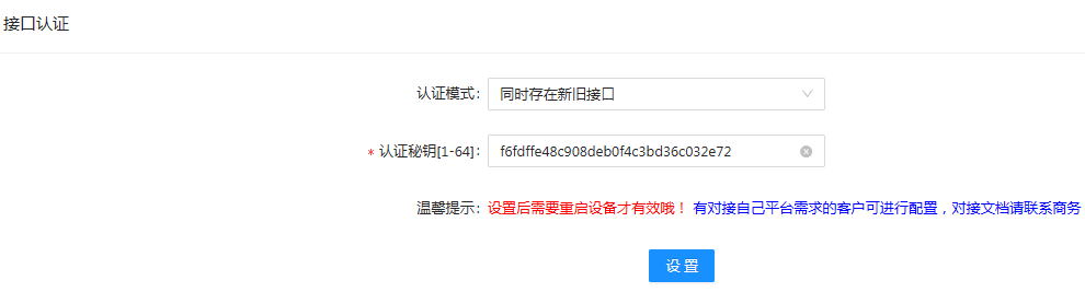
Figure 34
16.12 Time Configuration
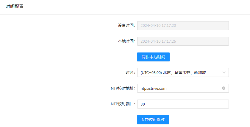
Figure 36
16.13 Advanced Configuration
Used to set the device name and to enable or disable the device login page. When it is enabled, you need to enter the device password every time you log in to the device; when it is disabled, you can directly enter the device backend without a password
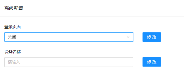
Figure 37
19 Device FAQ:
docs.html
20 Remote Video Playback
https://www.bilibili.com/video/BV1oV411y7Sk/
21 Remote Management of LAN Devices
https://www.bilibili.com/video/BV1U5411L7pS/
22 IP Addresses in 4G Mode and WiFi Mode
In 4G mode, the IP address is the fixed IP 192.168.0.15 and cannot be modified. This IP can be found on the LAN after connecting the network cable. To use this IP to enter the backend, you need to add an IP of 192.168.0.10 on the computer. For how to add an IP on the computer, see this link https://blog.csdn.net/zd1512149/article/details/139860822.
In 4G mode, if no network cable is connected, you need to use the remote address to enter. First bind the account to the cloud platform, and use the remote address: serial number.cloud.xstrive.com:9502
The same applies in WiFi mode
23 https Address Playback
There are two methods to play a video stream address in https format
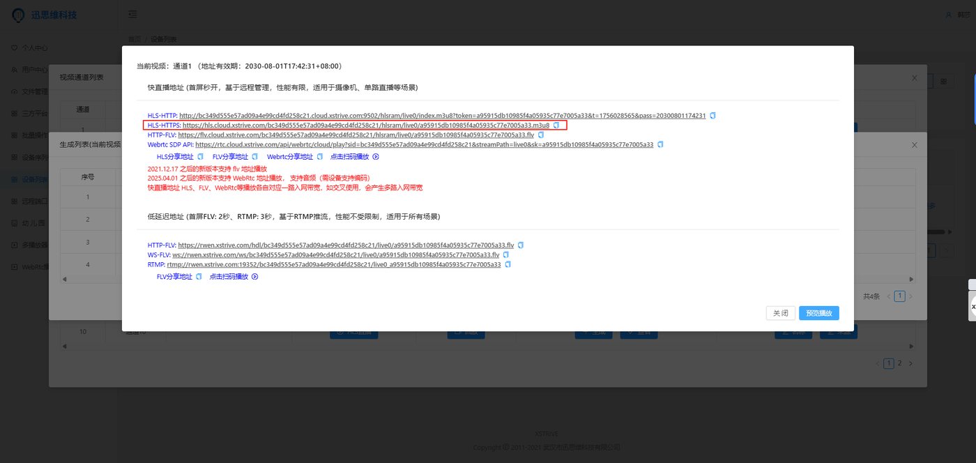
Method 1: the cloud platform generates an https stream address. Operation method: after registering on the cloud platform, bind the device through the serial number in the device list, click Play and log in, then click Generate (to use this address, the hls switch needs to be turned on. The address generated by the cloud platform can be played on both the LAN and the external network. Addresses generated from the cloud incur a traffic fee of 0.4/Gb)
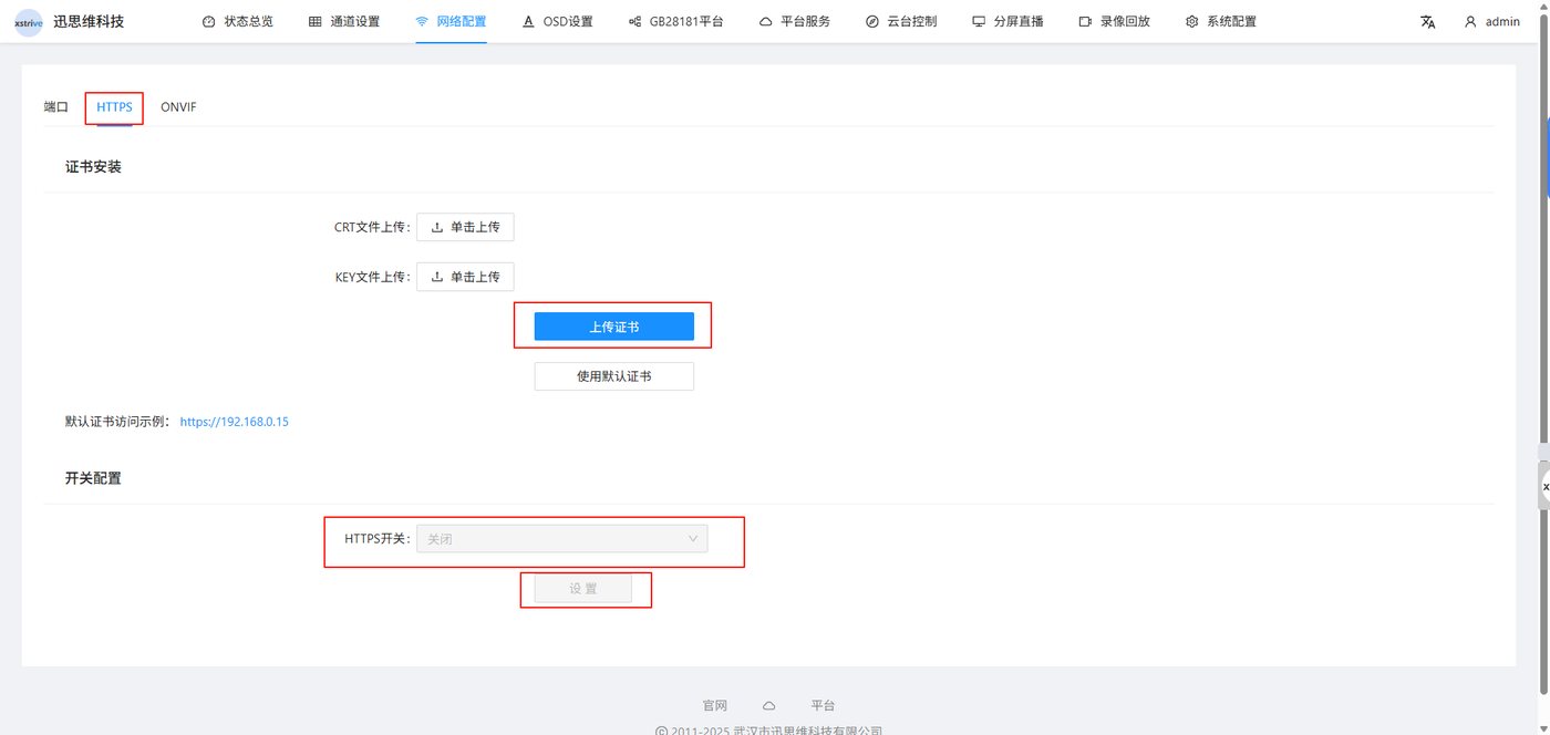
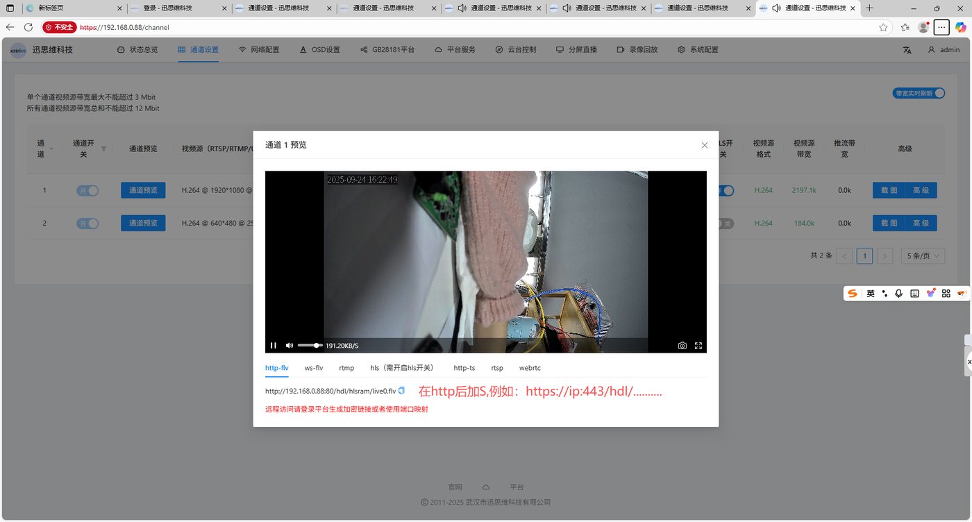
Method 2: in the device backend Network Configuration - Advanced Configuration, there is an https setting. You need to apply for the certificate yourself for upload; the default certificate can be used temporarily for testing. After setting the certificate, the format for logging in to the device IP is: https://ip (the address under Channel Preview is a LAN address and can only be played on the LAN)
24 Product Return, Exchange and Warranty Policy
Dear customer: Hello, thank you for using our products. We will provide you with high-quality after-sales service. The following are the product warranty service terms
1. Return and exchange are supported within seven days of purchase, and are not supported after 7 days (the seven days are counted from the day the express delivery is signed for)
2. Products purchased through Taobao, JD and other purchase channels are warranted with the order number, and corporate payment customers are warranted with the payment voucher; please keep your warranty voucher properly
3. Warranty period: within one year from the date of purchase from our company (within 3 months, for quality problem repairs, the customer bears the return shipping fee and our company bears the shipping fee; after 3 months, for quality problem repairs, the round-trip shipping fees are borne by the customer).
4. During the warranty period, under normal use, if the machine itself fails due to device material problems, and it is verified to be true, our company will provide free warranty and parts replacement;
5. During the warranty period, if damage is caused by improper use by the user, our company can provide paid repairs, and all costs incurred shall be borne by the user;
6. After the warranty period expires, our company can provide paid repair services
7. Free repairs are not supported within the warranty period under the following circumstances: ⑴. The product is damaged due to incorrect installation and improper operation ⑵. Damage caused by privately replacing parts or by repair and replacement by a party other than our company ⑶. Damage caused by other non-device factors, etc.
8. For second-hand products purchased from individuals or products purchased through channels other than our company's formal purchase channels, our company does not provide warranty services, after-sales repair services or technical support.