AK3918AV130 Module Specification
1 Overview
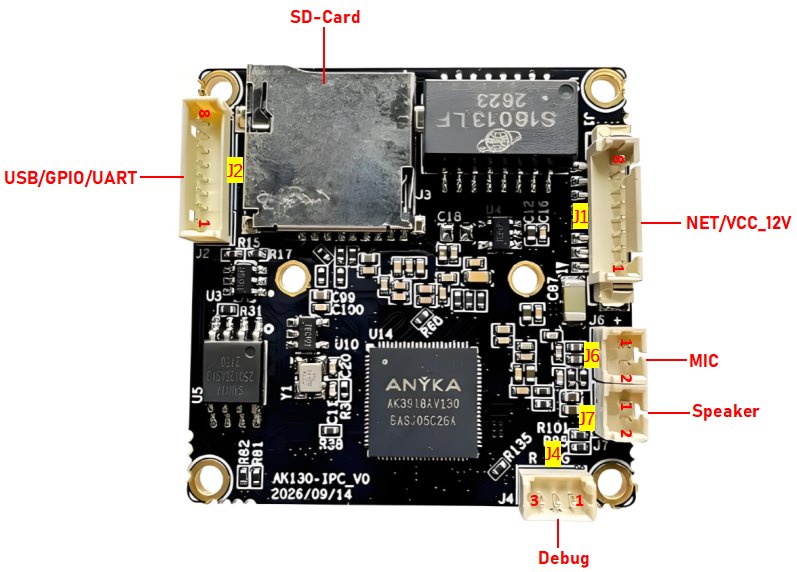
The AK3918AV130 module is a 38 mm × 38 mm square IPC main control board built around the ANYKA AK3918AV130 AIoT camera SoC. The chip is purpose-built for AIoT cameras: a dual-core 32-bit RISC CPU (up to 960 MHz) with integrated ISP, video processing unit and NPU, delivering high-quality image processing, low-bitrate video encoding and real-time AI inference for typical AIoT workloads such as object detection and tracking, face detection and recognition, and intelligent video surveillance.
The board integrates Ethernet, SD card, USB, UART, GPIO, MIC, speaker and IRCUT (IR-cut filter switching) interfaces plus audio paths, with a complete set of ESD protection, filtering and isolation networks around them, so it can drop straight into any IPC / camera product design.
| Item | Parameter |
|---|---|
| Product form | IPC / AI camera main control board |
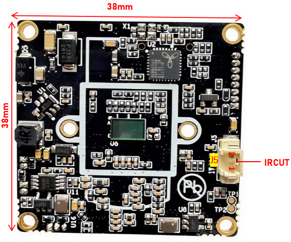
| Board size | 38 mm × 38 mm |
| Board silkscreen | AK130-IPC_V0 (date code 2026/09/14) |
| Main controller | ANYKA AK3918AV130 AIoT camera SoC (QFN88) |
| CPU core | Dual-core 32-bit RISC, up to 960 MHz |
| On-board memory | 512 Mibit DDR2 SDRAM |
| AI unit | Built-in NPU: object detection/tracking, face detection/recognition |
| Video encoding | H.264 hardware encode up to 2304×4096; JPEG up to 16384×8192 |
| Camera input | MIPI + DVP interfaces, two CIS inputs supported |
| Network | On-board Ethernet transformer interface (10/100M Ethernet) |
| Storage expansion | Micro SD socket (TF, XKTF-015-G, hot-plug detection) |
| Power supply | 12 V DC input (fed through J1 beside the Ethernet port) |
| Audio | Differential MIC input + Class-D speaker amplifier output |
| Other peripherals | IR-cut filter switching, IR_DET infrared detection input, IR fill light, reset button |
| Security engine | Secure boot; AES/DES/3DES; SM3/MD5/SHA; random number generator |
| Operating temperature | -20 °C to 80 °C (system level — confirm against the sensor and housing) |
2 Board basics
| Item | Parameter |
|---|---|
| Product form | IPC / AI camera main control board |
| Board size | 38 mm × 38 mm |
| Board silkscreen | AK130-IPC_V0 (date code 2026/09/14) |
| Main controller | ANYKA AK3918AV130 AIoT camera SoC (QFN88) |
| CPU core | Dual-core 32-bit RISC, up to 960 MHz |
| On-board memory | 512 Mibit DDR2 SDRAM |
| AI unit | Built-in NPU: object detection/tracking, face detection/recognition |
| Video encoding | H.264 hardware encode up to 2304×4096; JPEG up to 16384×8192 |
| Camera input | MIPI + DVP interfaces, two CIS inputs supported |
| Network | On-board Ethernet transformer interface (10/100M Ethernet) |
| Storage expansion | Micro SD socket (TF, XKTF-015-G, hot-plug detection) |
| Power supply | 12 V DC input (fed through J1 beside the Ethernet port) |
| Audio | Differential MIC input + Class-D speaker amplifier output |
| Other peripherals | IR-cut filter switching, IR_DET infrared detection input, IR fill light, reset button |
| Security engine | Secure boot; AES/DES/3DES; SM3/MD5/SHA; random number generator |
| Operating temperature | -20 °C to 80 °C (system level — confirm against the sensor and housing) |
3 Interface definition
3.1 Interface overview
| Designator | Interface | Type | Description |
|---|---|---|---|
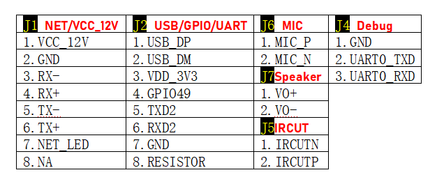
| J1 | NET / VCC_12V | 8-pin connector | Ethernet transformer differential pairs + 12 V power input + network status LED |
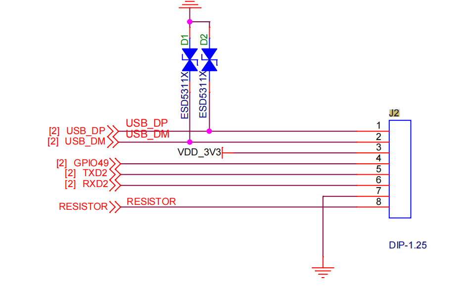
| J2 | USB / GPIO / UART | DIP-1.25 8P | USB 2.0, VDD_3V3, GPIO49, UART2 TX/RX, reset resistor footprint |
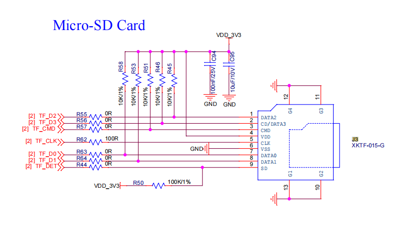
| J3 | SD Card | TF card socket | Micro SD (XKTF-015-G), hot-plug detection |
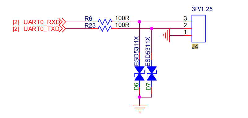
| J4 | Debug | 3P / 1.25mm | UART0 debug port (RX/TX/GND) with ESD protection |
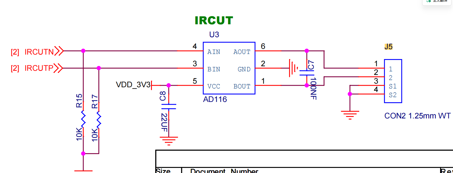
| J5 | IRCUT | 4P / 1.25mm | IR-cut filter control (IRCUTN / IRCUTP), white light / infrared switching |
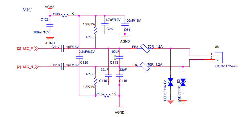
| J6 | MIC | 2P / 1.25mm | Analog microphone differential input (MIC_P / MIC_N) |
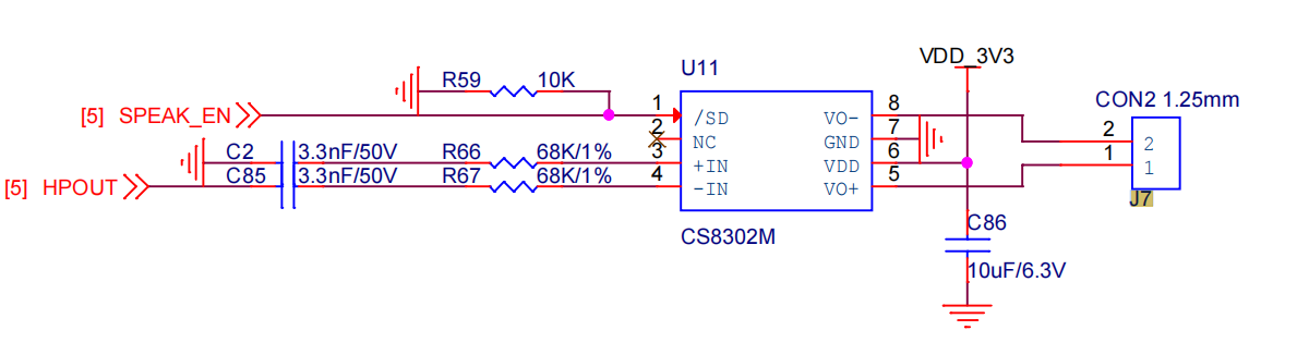
| J7 | Speaker | 2P / 1.25mm | Speaker output (VO+ / VO-) |
3.2 J1 NET / VCC_12V (8P)
| Pin | Signal | Note |
|---|---|---|
| 1 | VCC_12V | 12 V DC power input |
| 2 | GND | Ground |
| 3 | RX- | Ethernet differential RX − |
| 4 | RX+ | Ethernet differential RX + |
| 5 | TX- | Ethernet differential TX − |
| 6 | TX+ | Ethernet differential TX + |
| 7 | NET_LED | Network LED drive |
| 8 | NA | Reserved |
J2 USB / GPIO / UART (DIP-1.25 8P)
| Pin | Signal | Note |
|---|---|---|
| 1 | USB_DP | USB 2.0 D+ |
| 2 | USB_DM | USB 2.0 D− |
| 3 | VDD_3V3 | 3.3 V power output |
| 4 | GPIO49 | General-purpose GPIO |
| 5 | TXD2 | UART2 TX |
| 6 | RXD2 | UART2 RX |
| 7 | GND | Ground |
| 8 | RESISTOR | Spare resistor footprint (default pull-down / high-Z; measured to the GND side) |
J3 SD Card (Micro SD, XKTF-015-G)
| Pin | Signal | Note |
|---|---|---|
| 1 | TF_D2 | Data line 2 |
| 2 | TF_D3 | Data line 3 |
| 3 | TF_CMD | Command |
| 4 | VDD_3V3 | 3.3 V supply (100K/1% series current limit) |
| 5 | TF_CLK | Clock |
| 6 | TF_D0 | Data line 0 |
| 7 | TF_D1 | Data line 1 |
| 8 | TF_DET | Card detect |
| 9 | GND | Ground |
J4 Debug (3P / 1.25mm)
| Pin | Signal | Note |
|---|---|---|
| 1 | GND | Ground |
| 2 | UART0_TXD | Debug UART TX |
| 3 | UART0_RXD | Debug UART RX |
J5 IRCUT (4P / 1.25mm)
| Pin | Signal | Note |
|---|---|---|
| 1 | IRCUTN | Filter driver complementary output, N side |
| 2 | IRCUTP | Filter driver complementary output, P side |
| 3 | GND | Ground |
| 4 | S1/S2 | Spare switching contact |
J6 MIC (2P / 1.25mm)
| Pin | Signal | Note |
|---|---|---|
| 1 | MIC_P | Microphone + (isolated through bead FB3) |
| 2 | MIC_N | Microphone − (isolated through bead FB4) |
J7 Speaker (2P / 1.25mm)
| Pin | Signal | Note |
|---|---|---|
| 1 | VO+ | Amplifier output + |
| 2 | VO- | Amplifier output − |
4 Main controller specifications (AK3918AV130)
The AK3918AV130 series is designed for artificial-intelligence IoT (AIoT) cameras. Built on a dual-core CPU, it integrates an image signal processor (ISP), a video processing unit and a neural processing unit (NPU), delivering high-quality image processing, low-bitrate video encoding and real-time AI inference for object detection and tracking, face detection and recognition and intelligent video surveillance, while keeping power consumption low. In light-sleep mode the chip draws even less, noticeably improving product energy efficiency. For security it embeds a security engine with secure boot and data encryption to protect firmware integrity and runtime safety. UART, SPI, MMC/SD/SDIO, TWI, Ethernet and USB 2.0 peripherals make it highly extensible and quick to adapt to a wide range of end products.
| Category | Parameter |
|---|---|
| CPU | Dual-core 32-bit RISC CPU, up to 960 MHz |
| Memory | Built-in 512 Mibit DDR2 SDRAM |
| Neural processing unit | Object detection/tracking, face detection/recognition and other algorithms |
| Camera | MIPI and DVP interfaces, two CIS inputs supported |
| Image pre-processor | Image scaling and flipping; rectangle drawing and filling; privacy masking; image OSD |
| Image signal processor | Auto white balance, auto exposure, auto focus; gamma correction; bad-pixel correction; 3D/2D noise reduction; edge enhancement |
| Video encoder | H.264 encoder up to 2304×4096; JPEG encoder up to 16384×8192 |
| Audio codec | 1 × 24-bit Sigma-Delta DAC; 1 × 16-bit Sigma-Delta ADC |
| Peripheral interfaces | Ethernet, USB, SPI, MMC/SD/SDIO, UART, TWI |
| Security engine | Secure boot; AES/DES/3DES encryption and decryption; SM3/MD5/SHA; random number generator |
| Package | QFN88 |
5 Interface circuit notes
NET / VCC_12V (J1)
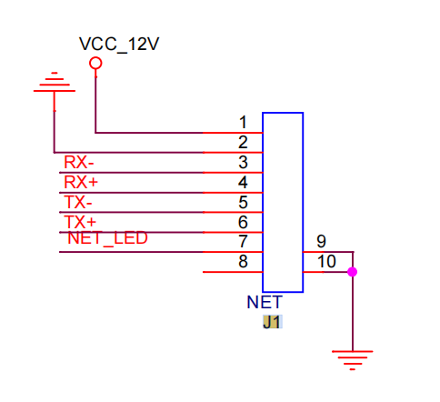
An on-board Ethernet network transformer brings the RX±/TX± differential pairs straight out; the 12 V supply shares the same 8-pin connector with the pairs, and every differential line is fitted with an ESD5311X protection device.
Debug (J4)
UART0_TXD / UART0_RXD each run through a 100 Ω resistor (R6 / R23) before leaving the board, with ESD5311X bidirectional ESD protection and a discharge path to ground via R52.
USB / GPIO / UART (J2)
USB_DP / USB_DM each have ESD5311X bidirectional protection; VDD_3V3 leaves the board through the D1/D2 ESD diode array; GPIO49, TXD2 and RXD2 are direct SoC signals; the RESISTOR position is for product-level resistor configuration.
MIC (J6)
MIC_P / MIC_N differential input; the analog supply VCM3 is filtered by R108 (1K) plus C25 (4.7 uF/10 V); bias resistors R105 / R106 (1.2K/1%); coupling capacitors C117 / C118 and C120; both microphone lines leave the board isolated through beads FB3 / FB4.
Speaker (J7)
Uses a CS8302M Class-D amplifier; the SPEAK_EN mute control is pulled up through R59 (10K); the differential HPOUT input is high-pass filtered by R66 / R67 (68K/1%) and C2 / C85 (3.3 nF/50 V); outputs VO+ / VO-.
IRCUT (J5)
Uses an AD116 driver; IRCUTN / IRCUTP are complementary outputs with 10K pull-up/pull-down each (R15 / R17); J5 additionally provides spare S1/S2 switching contacts.
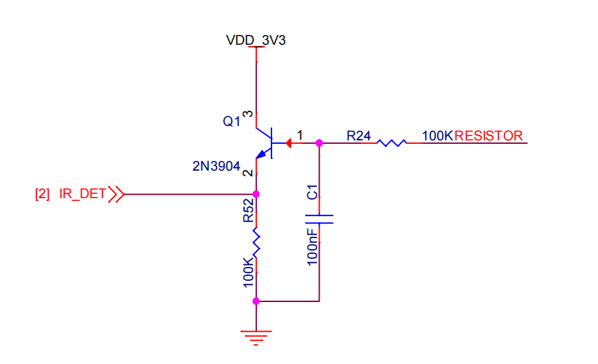
IR_DET infrared detection
Q1 (2N3904) performs level shifting: the base is pulled down through R52 (100K) and takes IR_DET as input; the collector is pulled up to VDD_3V3 through R24 (100K) and drives the signal on the RESISTOR side.
SD Card (J3)
Socket model XKTF-015-G; TF_D0~D3 each have a 10K/1% pull-up plus a 0 Ω series resistor; TF_CLK runs through R62 (100R); VDD_3V3 is supplied through R50 (100K/1%).
6 Key bill of materials (BOM extract)
| Designator | Part | Parameter / model | Function |
|---|---|---|---|
| U14 | SoC | ANYKA AK3918AV130 (6A5-05C264) | Main controller |
| U11 | Amplifier | CS8302M | Speaker driver |
| U3 | Driver | AD116 | IR-cut driver |
| Q1 | Transistor | 2N3904 | IR_DET level shifting |
| J1 | Network transformer | — | Ethernet physical layer |
| J3 | TF card socket | XKTF-015-G | Micro SD storage |
| FB3 / FB4 | Ferrite bead | 70Ω / 1.2A | MIC signal isolation |
| D1 / D2 / D6 / D7 | ESD | ESD5311X | USB / UART ESD protection |
| C86 | Capacitor | 10uF/6.3V | Amplifier supply decoupling |
| C8 | Capacitor | 22uF | IR-cut supply decoupling |
7 Usage and design notes
Power: pin 1 of J1 (VCC_12V) is the only 12 V input. The network port and the power input share one connector, so the harness must keep both the 12 V supply and the differential pairs reliable.
Debug: UART0 is only brought out on J4 — share ground when debugging and use this port to download firmware.
IR-cut driver: IRCUTN / IRCUTP are complementary outputs and must not drive high-current loads directly; leave headroom in the driver circuit for the filter switching load.
MIC bias: MIC bias comes from R105 / R106 on the board; the external microphone must be electret / condenser type and the ground must be shared.
TF card power: TF power is fed through R50 (100K) in series — verify the voltage drop with large high-speed cards and move to a lower resistance if needed.
ESD: USB and UART already carry on-board ESD protection, but chassis grounding and system-level ESD design are still required.